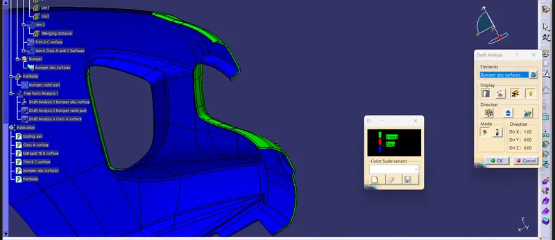
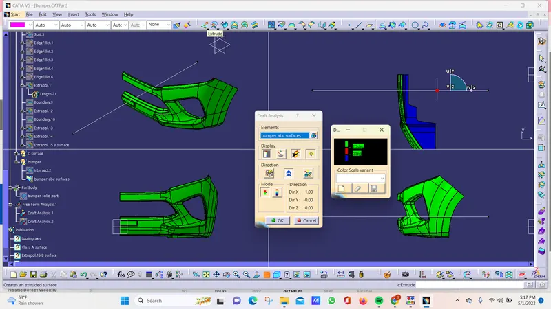
Week 9 - Challenge 3 - Bumper
Tooling Axis (Pull Direction, Tooling Direction):
In Molding, machine arrangement is given to open the mould along a direction which is known as Tooling Direction.
In other words. The mould is built from two separate halves (Core and Cavity) and tooling direction basically defines the direction of mould pulls apart.
Tooling direction is known as primary direction.
Tooling axis: The direction in which the mold or core and cavity opens is the tooling axis.
STEP-01
Connectivity of Class-A surface.Checking the connectivity of the surface, this can be done by creating boundaries or by simply using the join option such that any openings can be easily visualized.
STEP-02
Analyse visually for the best possible tooling axis.
A Dummy tooling axis will be directly created using point-direction command.
Checking possibilities (clearances) in all the directions of axis and find what are the problem creation parts of the component or model.
The clearance checking along all the axis direction will be done by creating an intersection along an axis on a plane with the model and constructing two lines contact with the walls, the line bisecting the two lines and passing through the point will be the tooling axis.
But here I have created a tooling axis. First of all I extract a base surface and create a mid point on it. And then I create a line through this point with perpendicular to base surface. And then I performed draft analysis ans I saw every thing is ok. Then finally it is my tooling axis.
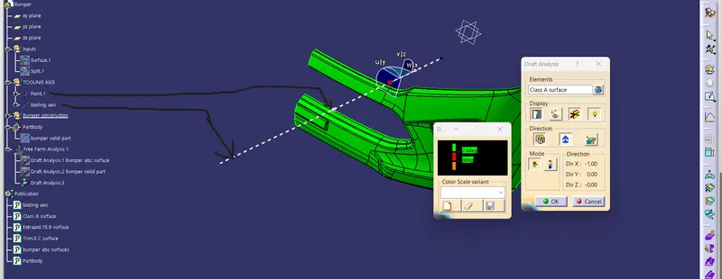
Draft Analysis:
The Draft Analysis command enables you to detect if the part you drafted will be easily removed. This type of analysis is performed based on colour ranges identifying zones on the analyzed element where the deviation from the draft direction at any point, corresponds to specified values.
Tooling direction is the main consideration for plastic part and mould parts because it defines the movement of the mould part and the possibility of the plastic part coming out from the mould part (Core and Cavity).
Draft Analysis:Draft analysis is done after determining the tooling axis, draft analysis is used to check whether the minimum draft (3 degrees) is maintained or not.
Compass is used to define the draft direction.
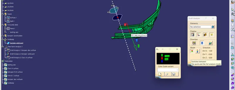
If the minimum draft 3 degree is provided the whole component changes in to green colour.
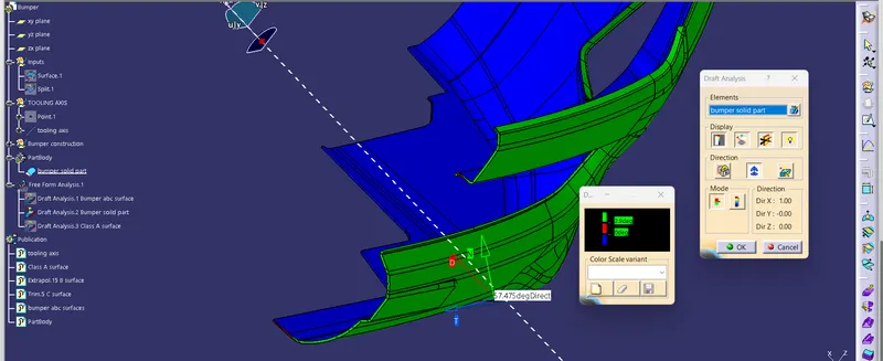
in this case C surfaces has little bit red color. so change the draft degree is 2.5 in that defact was clear