Wiring harness design in CATIA V5 - 3D modeling Week 2 Challenge
Wiring harness Design:
Connectors were given to define them in Electrical environment.
Descreption is given below:
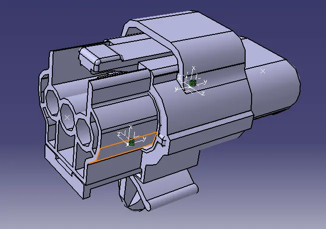
1) Connector- 174357
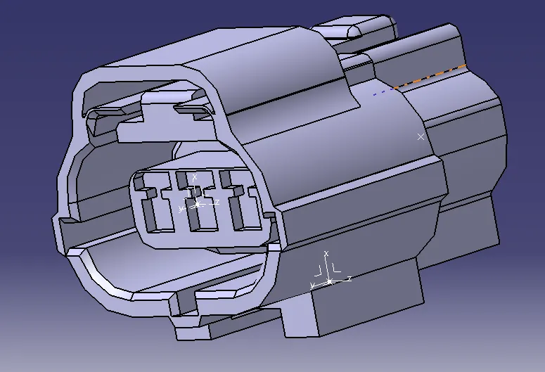
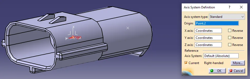
Points are created for the axis system.
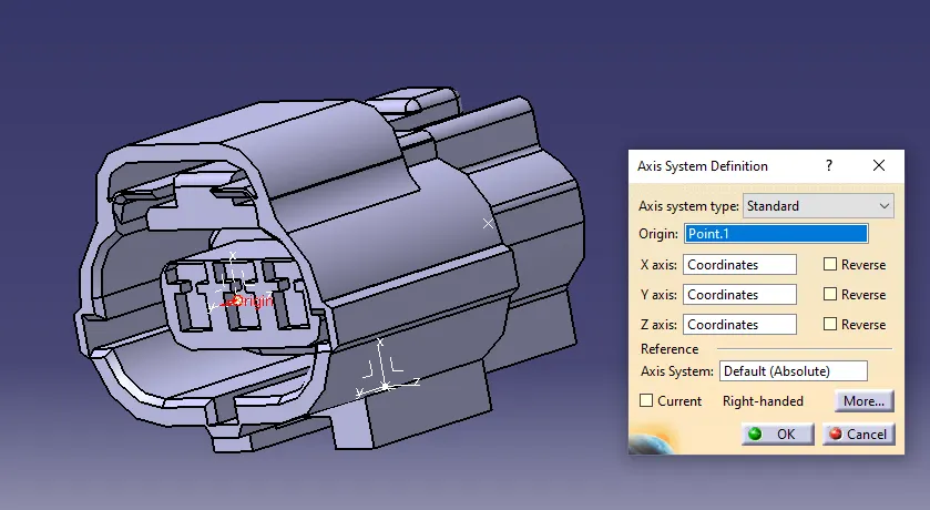
X- axis kept in postion for alignment of shocket to it's mating shocket.
Y-axis kept in such a way that it will be oriented same for mating connector in assembly.
Z-axis kept for lock mating orientetion.
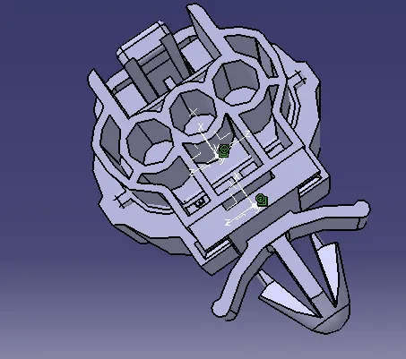
After that termination are defined, in this case 3-terminals are required.
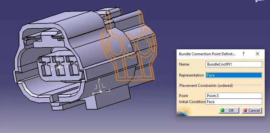
Bundle connection point is given.
Connector Connection is defined.
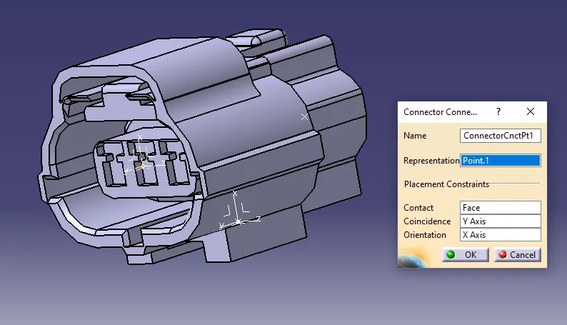
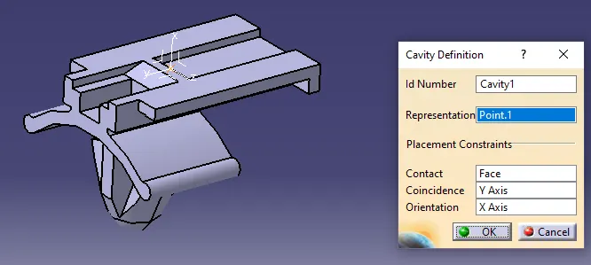
For the mounting of the shocket on part cavity is given where clip will be assembled. For that cavity point is defined.
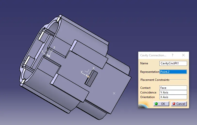
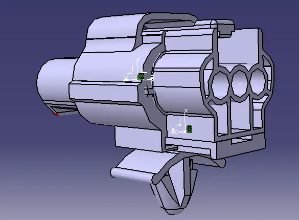
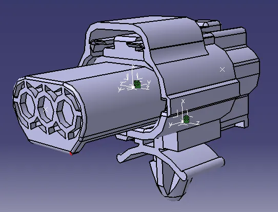
Same procedure is followed for male connector images are given for 881774.
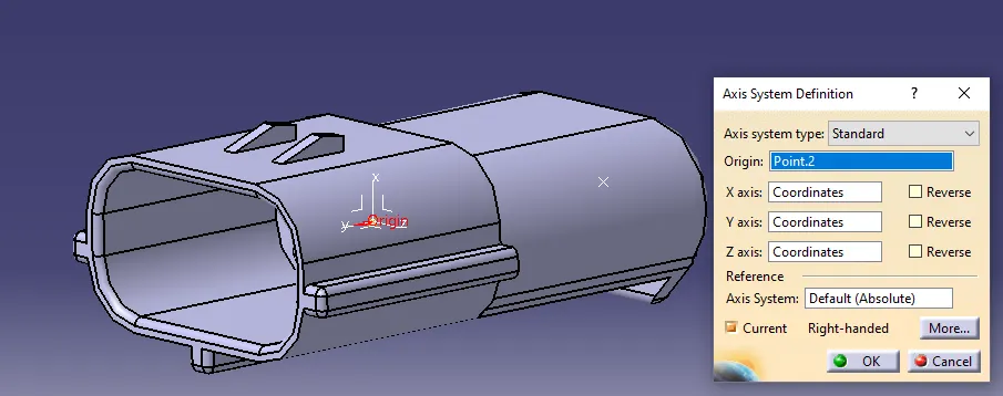
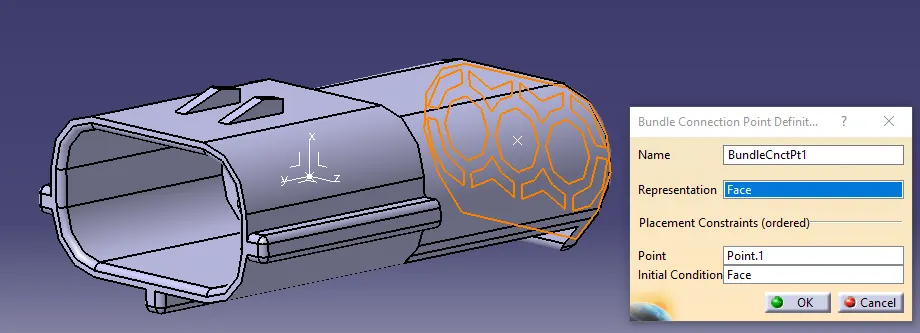
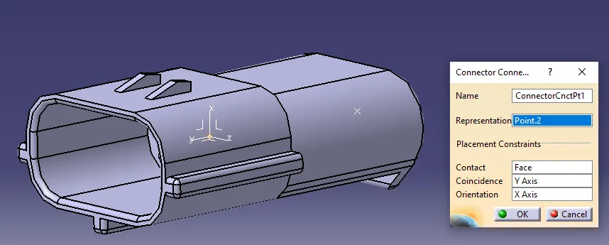
Clip is defind as a cavity, by doing same procedure as above.
For Assembly connect electrical devices option is used.
By inserting two connectors coincedence, surface, and orientation type of constrains are defined.
By defining these contraints assembly is completed.
Images of assembly are given below: