Wiring harness design in CATIA V5 - 3D modeling Week 2 Challenge
Wiring harness design in CATIA V5 - 3D modeling Week 2 Challenge
AIM:
Download following connectors & Connector clip cad data from given link & define it as Electrical Connector using Electrical Part design Workbench. Define all the necessary properties to Connectors & Clip.
1. Deutsch DT06 – 08SA
2. Tyco 174357-2
3. Tyco 85229-1
INTRODUCTION TO WIRE HARNESS:
A Wire harness is a specially designed system that keeps numerous wires or cables organized. It is a systematic and integrated arrangement of cables within an insulating material.
The purpose of the wiring assembly is to transmit a signal or electrical power. 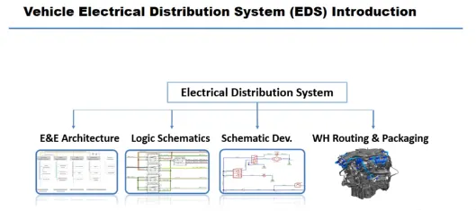
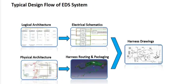
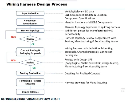
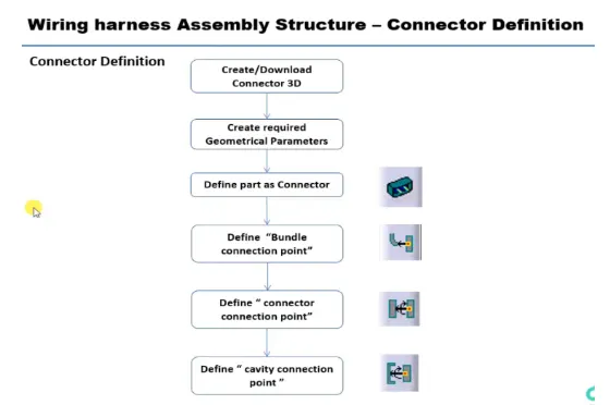
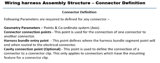
CONNECTOR DEFINATIONS IN CATIA V5
1. Deutsch DT06 – 08SA
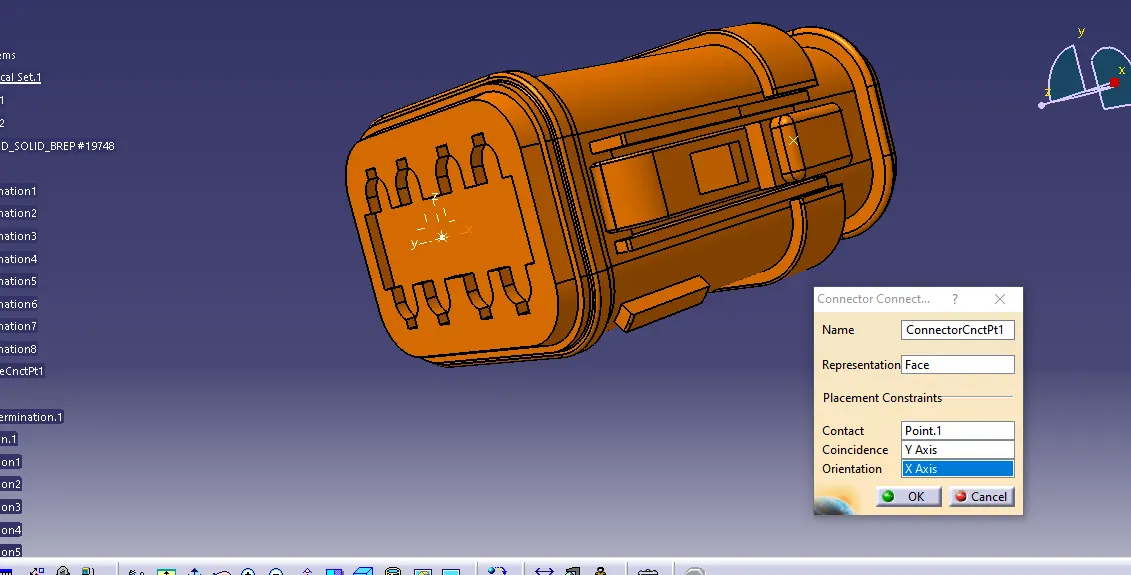
Connector connection point:
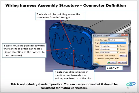
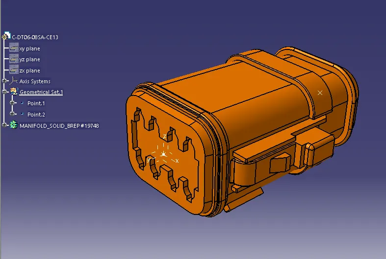
- Create midpoint on the contact face which will be normal to wire bundle insertion.
- Create Axis System with respect to the point which we have created and defining the axis direction as shown below,
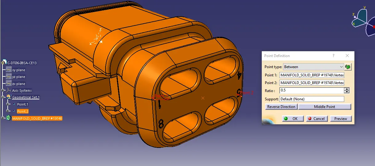
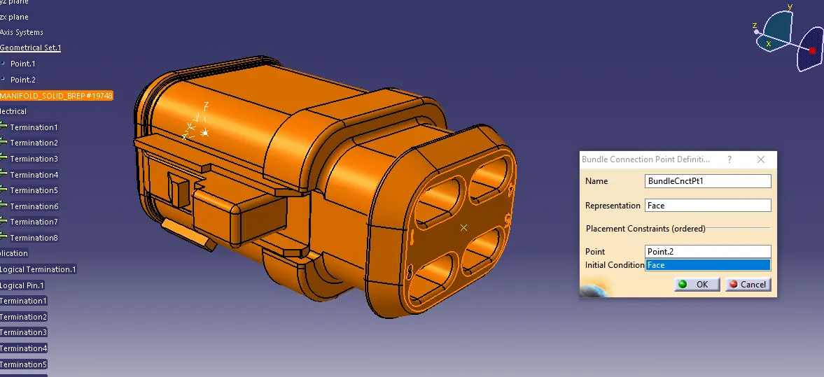
· Bundle connection point:
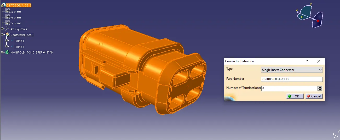
Switch to 'Electric Part Design':
- Define the part as connector in catia, give no. of termination as 8 because we have 8 entry points for wire.
- Define Bundle connection point
· Define connector connection point
2.Tyco 174357-2 :
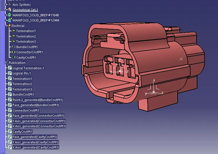
- Create midpoint
- create Connector connection point
- create Connector connection axis system
- create cavity connection point
- create cavity connection axis system
- Switch to Electric part design and define part as connector
- Define Connector connection point and cavity connection point
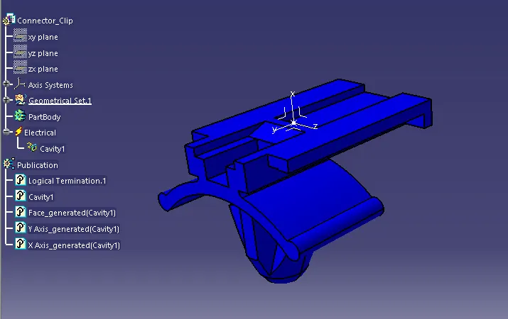
3. Tyco 85229-1 :
- Create midpoint
- create cavity connection point
- create cavity connection axis system and orientation should be same as in connector
- Switch to Electric part design and define part as Mounting Equipment
- Define cavity connection point
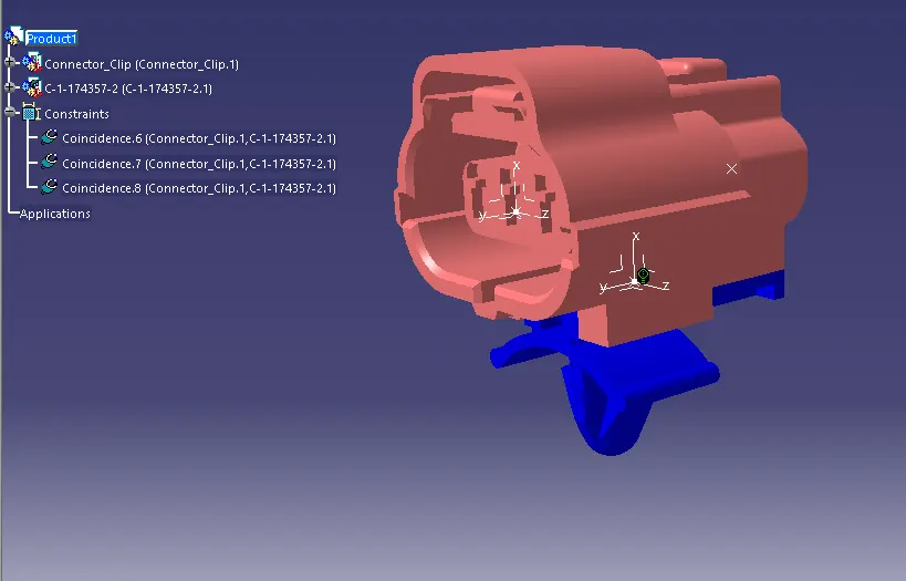
Electric Assembly Design
- Import Connector and cavity / mounting clip.
- Select Defining Electric connection
- select cavity and then connector
Conclusion:-
Defined all the necessary properties to Connectors & Clip ic Done.