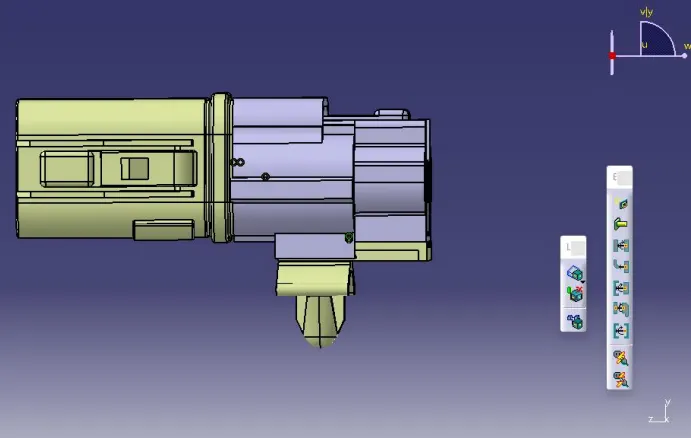
Wiring harness design in CATIA V5 - 3D modeling Week 2 Challenge
Solution
Objectives
To define the following connections and connector clip CAD parts as an electrical connector using the “Electrical Part Design” Workbench, get the data from the provided links. Create Connectors and Clips with all the required properties defined. The geometrical features (point, axis) must be defined before electrically defining a connector.
1) Deutsch DT06 – 08SA
Define Point and Axis for Connector Connection Point After downloading the CAD part and opening it in CATIA, start defining the point and axis of the connector by firstly switching to the “Part Design” workbench.
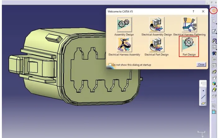
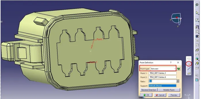
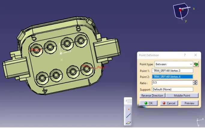
Create a midpoint on the contact face that will be used for regular wire bundle insertion in the workbench for the component. Press on the point icon “.” from the available tools in the “Part Design” workbench. Specify the point type to be “Between” in the popped-up window, and then select two points that will allow the center point to be placed at the desired location.
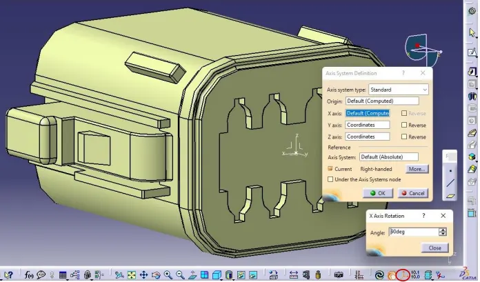
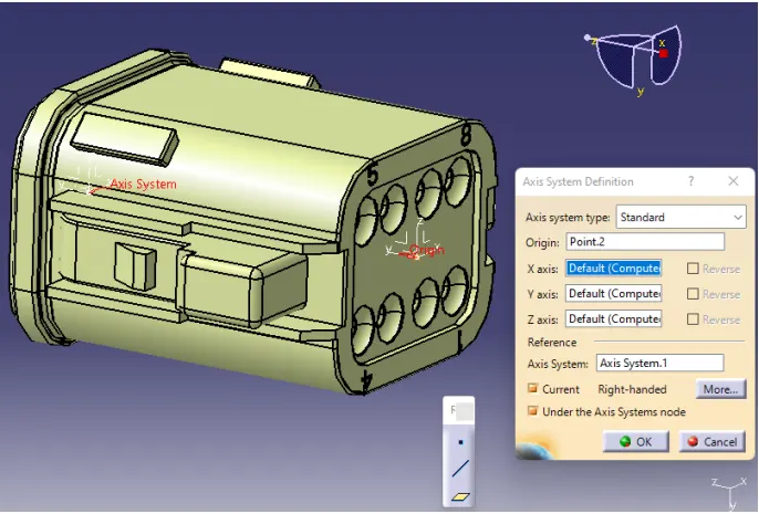
Create an axis system referencing the newly generated point and specifying the axis direction by clicking on the axis icon in the bottom toolbar. The x, y, and z axes can be customized in any direction. However, the common design trend is to maintain the direction of y-axis towards the insertion point, the x axis to the right (or left) direction, and the z-axis to top (or bottom) direction. Also, it is very important to maintain the same directions for the axes at all the points included in the assembly or design (including other connectors, mounting clips, supports, or any other point in the same connector surface).
Define Point and Axis for Bundle Connection Point
Point
Axis
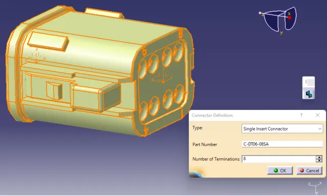
Switch to ‘Electric Part Design’ workbench
In CATIA V5, define the component as a connector and enter an 8 for the number of terminations because there are 8 wire entry points.
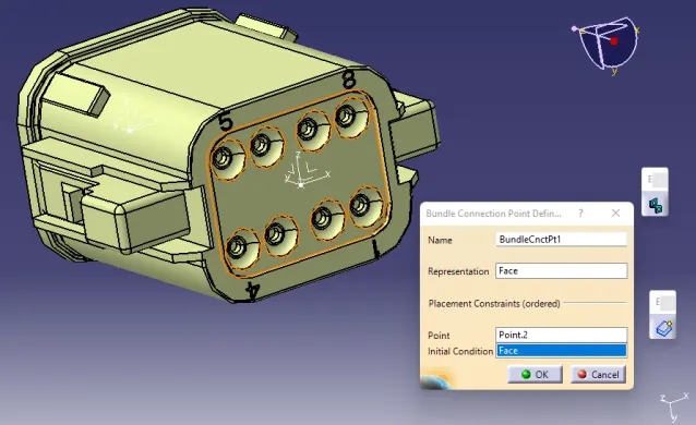
Define Bundle Connection Point
The highlighted face is specified in “Representation” and “Initial Condition”
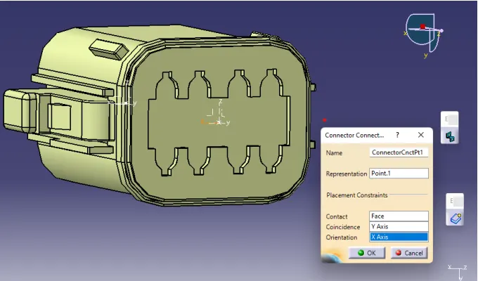
Define Connector Connection Point
2) Tyco 174357-2
Define Point and Axis for Connector Connection Point
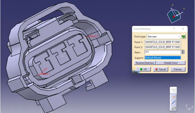
Create a midpoint on the contact face that will be used for regular wire bundle insertion in the workbench for the component.
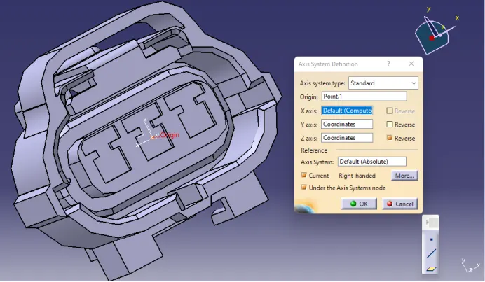
As shown below, create an axis system referencing the newly generated point and specifying the axis direction.
Define Point and Axis for Bundle Connection Point
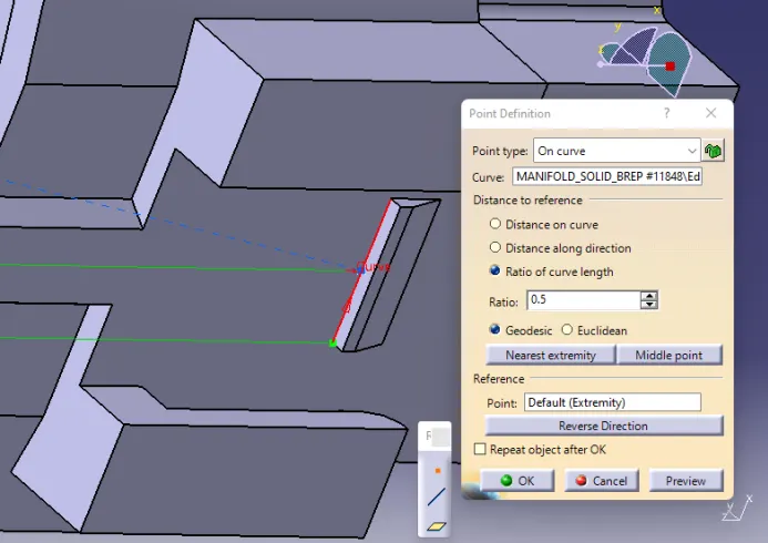
Point
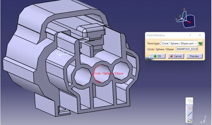
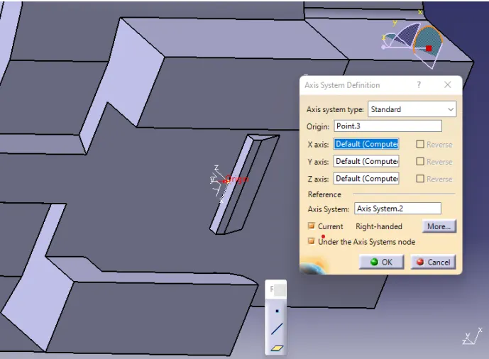
Axis
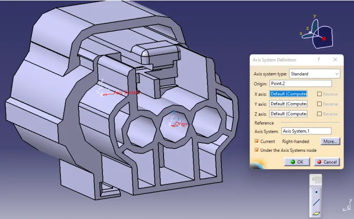
Make a Connecting Point in the Cavity
Create a Cavity Connection Axis System
Switch to the ‘Electric Part Design’ Workbench
In CATIA V5, define the component as a connector and enter a “3” for the number of terminations because there are 3 wire entry points.
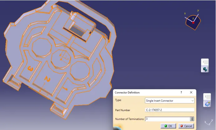
Define Bundle Connection Point
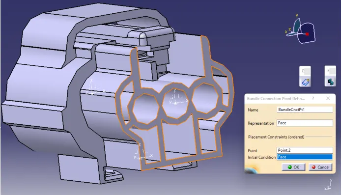
Define Connector Connection Point
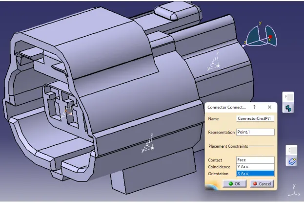
Define Cavity Connection Point
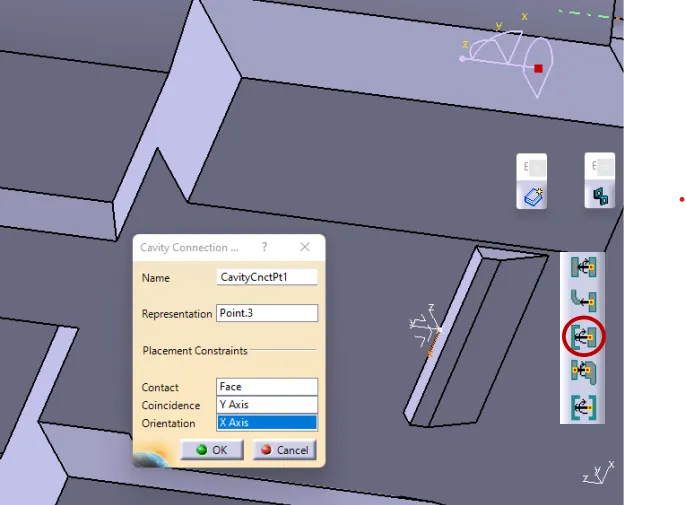
3) Tyco 85229-1
Create a Midpoint
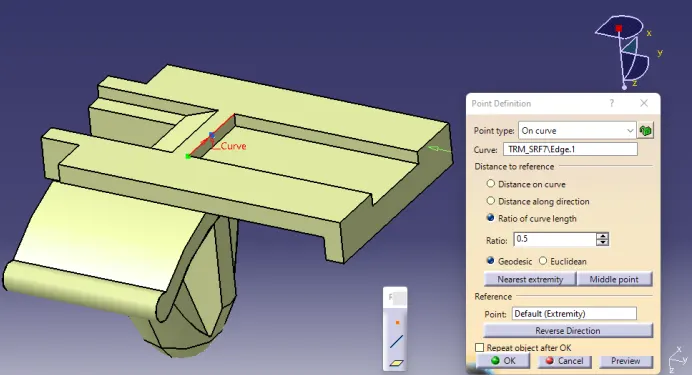
Create an Axis System
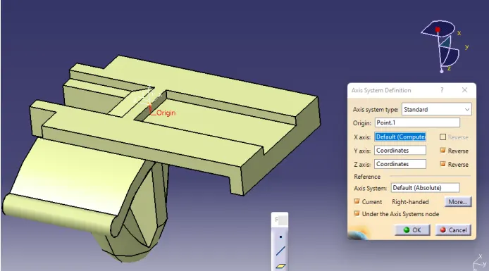
Switch to the 'Electric Part Design' Workbench and Define the Part as a Mounting Equipment
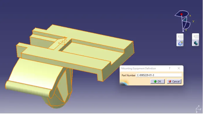
Define the Cavity Connection Point
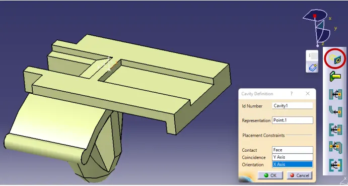
Switch to ‘Electric Assembly Design’ Workbench
Copy and Paste all the Three Electrically Defined Parts in that Workbench
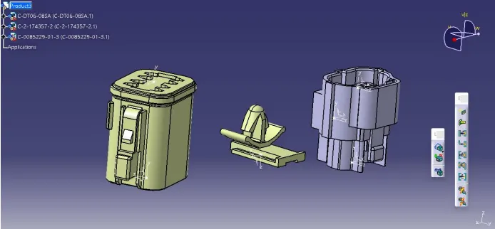
Connect the Mounting Clip and the Tyco 174357-2 Connector by Using ‘Connect Electrical Devices’ at the Pre-Defined Cavity Connection Point
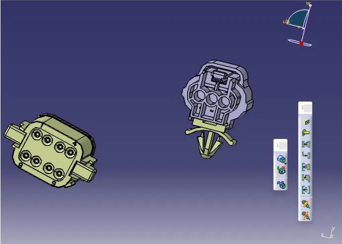
Connect the other Two Connectors Electrically through the Connector Connection Point