Wiring harness design in CATIA V5 - 3D modeling Week 2 Challenge
WIRING HARNESS DESIGN IN CATIA V5-3D MODELING
AIM:
The given connectors and connector clips has to define as a electric component to used in harness routing process by defining its geometrical properties and other electrical construction definitions in electrical part design and assemble the connector and mounting clips in electrical assemble design.
INTRODUCTION:
WIRING HARNESS:
Wiring harness is the process of systematic arrangement of all wires and cables as a single organized unit with in a bundle of insulating material. The purpose of wiring harness is to transmitting the power or electrical signals from one location to another location of device to run the operation.
In the industrial or other big applications there are many wire cables in single location for transmitting required data, in that case there need lot of cables, wires, connectors and other electrical devices. If we cannot provide proper arrangement for the wiring cable it causes the damage and hazard to the users.so that all the cables drawn through the single insulating bundle and bound together by ties, straps, cable lacing, electrical tapes etc.
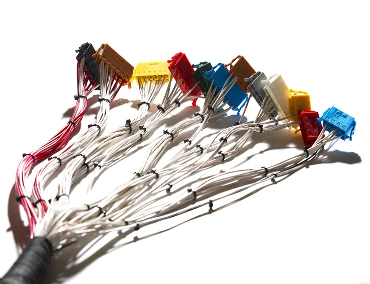
What is Automotive wiring harness ?
An automotive wiring harness is a set of wires, cables, terminals and connectors are drawn throughout the entire vehicle inside the plastic and sheet metal parts for different applications like, head light, tail lamp, music system, wind shield glasses and wiper motors etc.to transmitting the power and signals for contacting sensors, actuators, controllers, air bags etc.
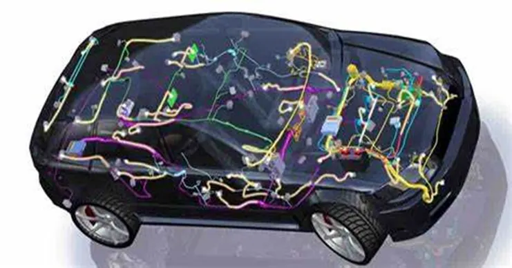
In wiring harness comprises the wires, cables, connectors, terminals, clips, clamps and mounting clips etc.
CONNECTORS:
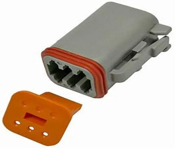
Connectors are the electrical components which are connects or joint the other wires, cables and other suitable terminal connectors based on the necessity in other end.
Connectors are most flexibly used components to branching and connecting other wires .there are many type of connectors available for automotive purpose.
CLIPS&CLAMPS:
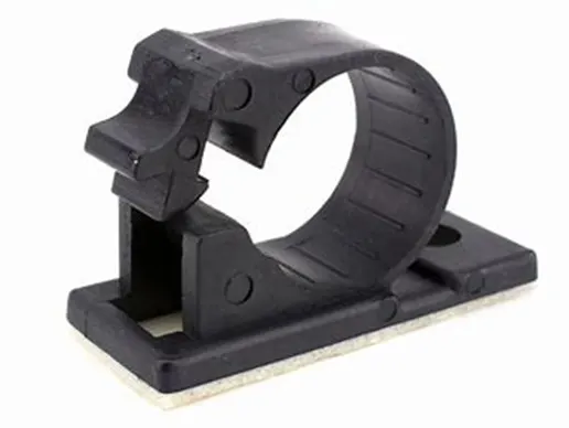
These are the supporting parts for the connectors in wiring harness.in the a vehicle there are lot of applications available and using many connectors through out the vehicle. But for every connector needs the support or any mounting to fix it rigidly in the given location. For that we are using many connector clamps and clips .
WIRING HRNESS DESIGN PROCESS:
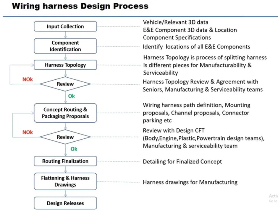
The below chart shows the brief idea on harness design process.
WIRING HARNESS ASSEMBLY STRUCTURE:
The following is the process for the assembly structure of connector in wiring harness process, it is the initial stage of wiring process.
Start the wiring process with the available 3D cad data of connector or make the part design if we don’t have available cad files. For readily connector cad files there are many sources in the market, from that we can directly download and used in the application.
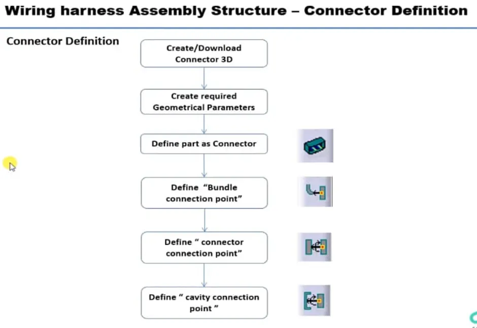
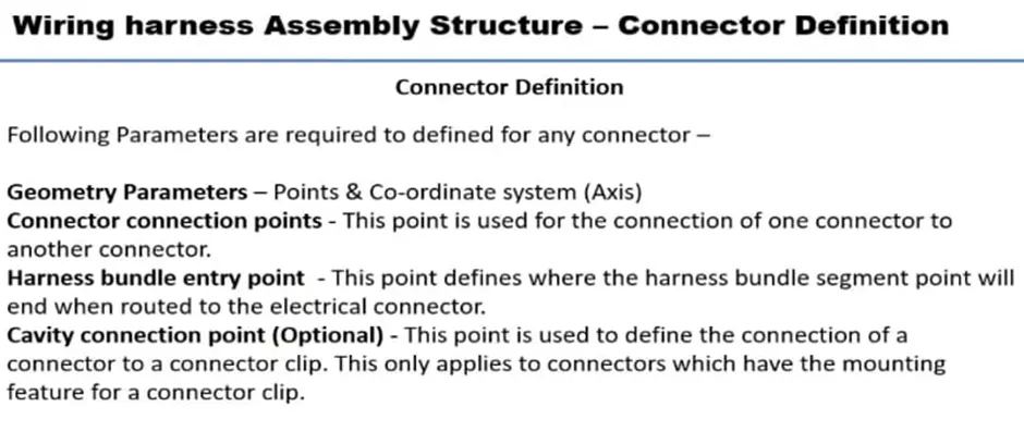
After downloading the cad file, have to define the geometrical parameters for the part connector.
To define the connector in electrical work bench and other parameters need the geometrical parameters initially.
As follow:
PROCEDURE AND TOOLS:
Deutsch DT06 – 08SA
*first create a point on the normal face of the connector
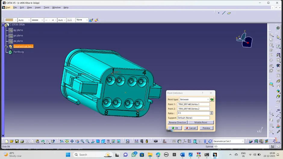
*create the axis system with respect to the created point as a representation. As below
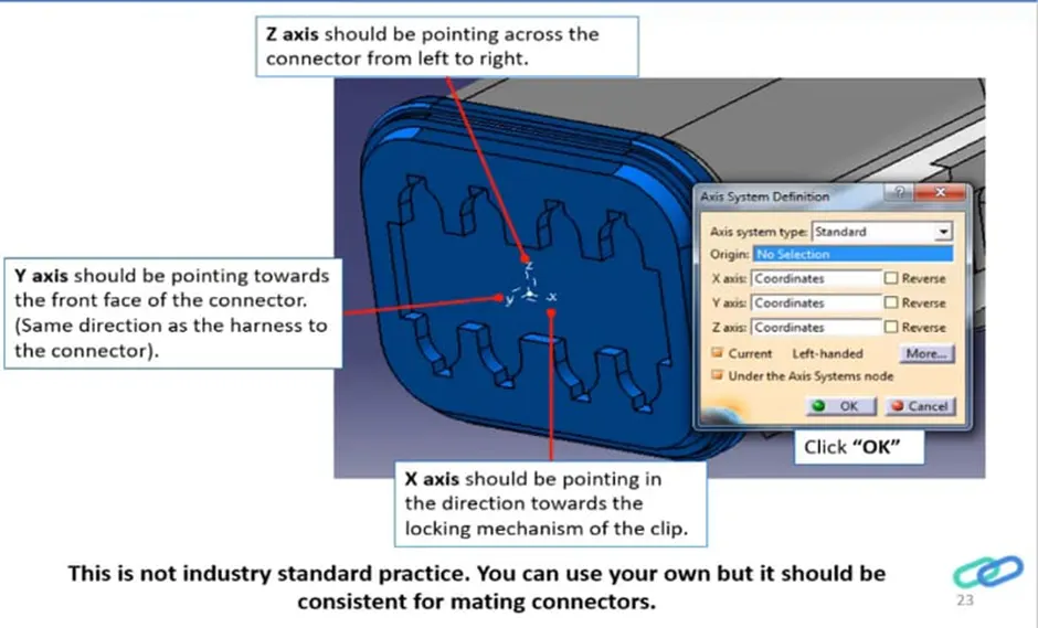
The axis rotation must should be in the appropriate manner because to avoid the miss alignment in the assembly time.
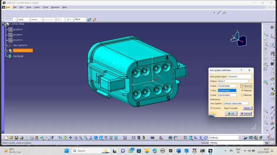
After defining all geometrical parameters, now switched into the ELECTRICAL PART WORK BENCH.
Connector definition:
Now the connector defined as electrical connector in electrical part workbench by selecting the connector definition.
Where it is asking type, part number and number of terminations. Enter as per required.
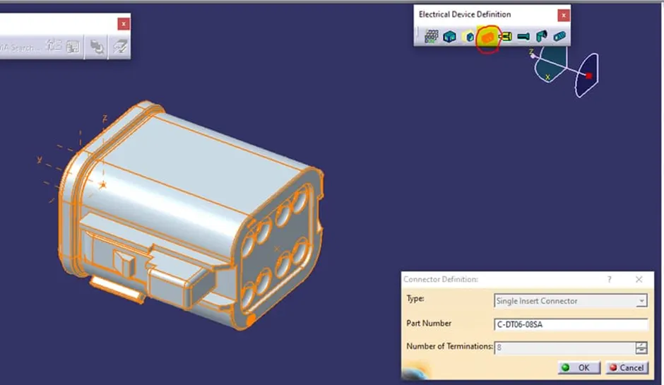
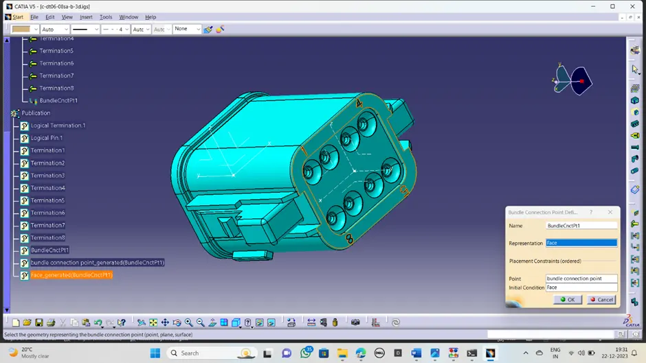
Bundle connection point:
*define the bundle connection point in the bundle connection side by choosing appropriate side and respective geometric parameters.
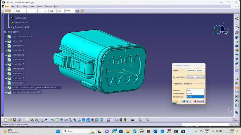
Connector connection point:
*define the connector connection point in the connector coming side by selecting the created point contact face, coincidence side and orientation as below.
2. Tyco 174357-2
In our challenge the 2nd assignment is the TYCO 174357 connector.
point
*First collect the or download the available connector 3D file from the source.
*Create the midpoint by selecting the either normal face both sides of connector.
*Create the point for connector connection point
*Create the point for bundle connection point in the bundle side
*Create the point for cavity connection point in the side of where the mounting clip housing provided.
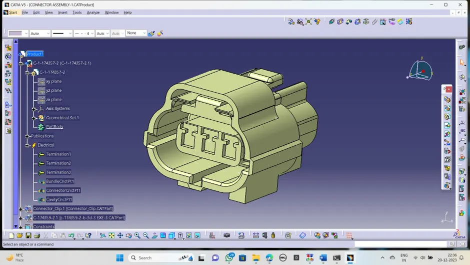
Axis system
*Create the proper axis system by selecting the origin or representing points available on connectors for connector connection.
*Create the axis system for cavity connection provided on it.
Axis must be followed some assembly and electrical constrain factors to assemble properly for furtherly.
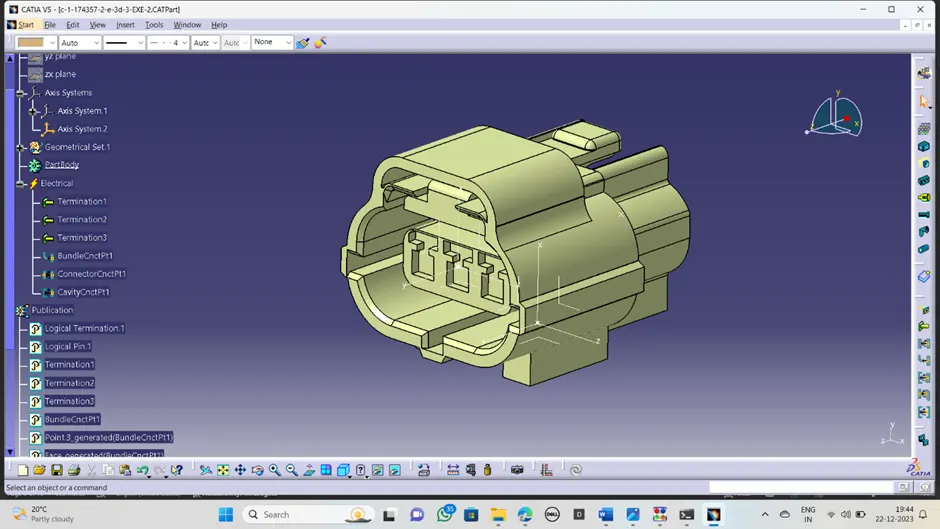
Now switched into the ELECTRICAL PART DESIGN.
Connector definition:
*Now the part has to be defined as the connector
*Create the bundle connection point by considering contact, coincidence and orientation.
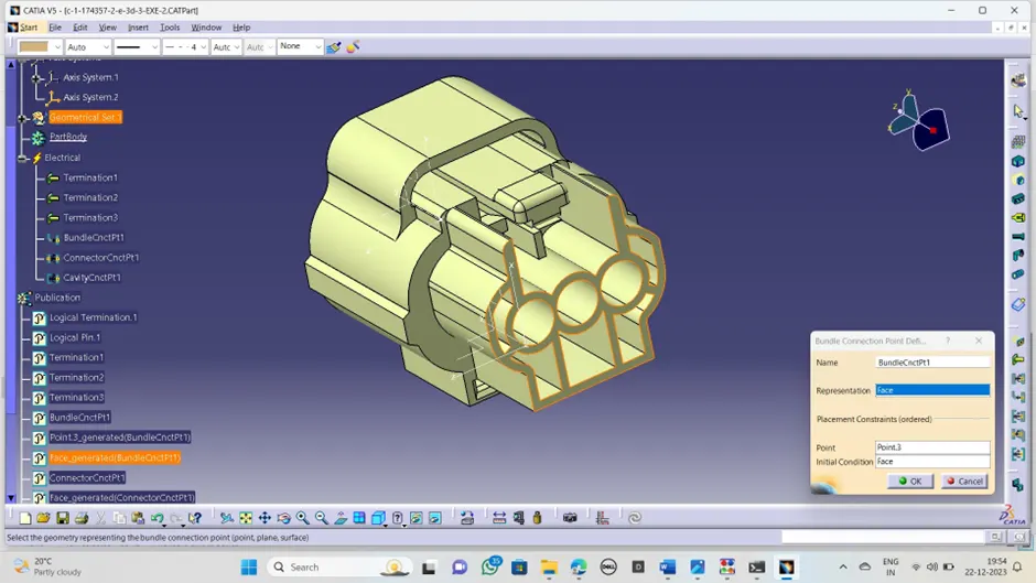
*Create the connector connection point by taking the point and axis system provided for it.
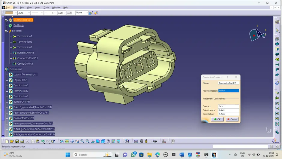
*create the cavity connection point in the cavity mounting side by taking provided point and axis system as a reference.
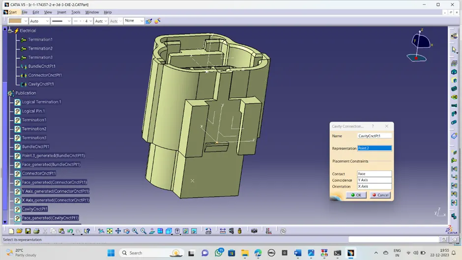
3.TYCO 85229_1
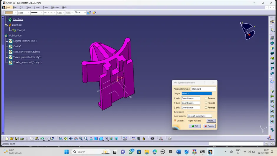
*Create the midpoint for cavity connection point at the mounting place
*Create the axis system with respect to the point. the axis orientation and coincidence of connector and connector clip should be same in direction.
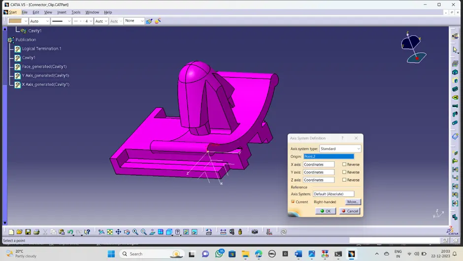
Now switched into the electrical part design:
*Create the cavity connection point with respect to the point and axis system provided on connector clip.
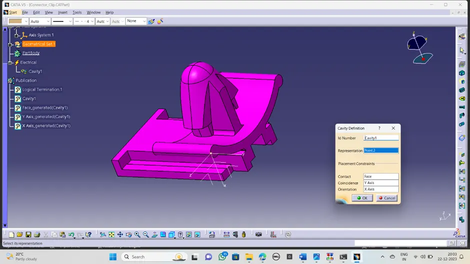
Now connector and connector mounting clips are readily available to assembling together.
So ,now switched into the electrical assemble design work bench.
ELECTRICAL ASSEMBLY DESIGN:
*Now import the both readily available parts into the product design workbench
*Positioning the connector clip exactly the way it has to assemble towards the connector mounting hose.
*Select the connect electrical device and click on connector clip and connector, there showing the connector cavity point in active mode.
*Click on ok then it assembled together as below exactly.
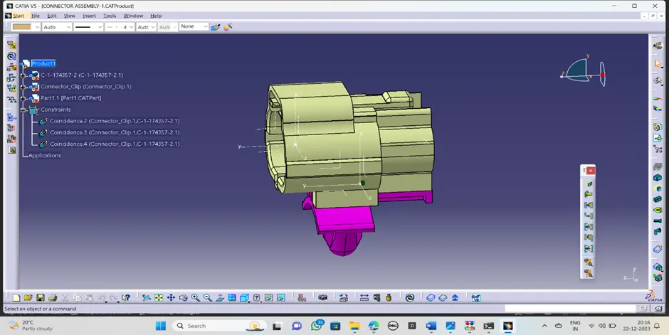
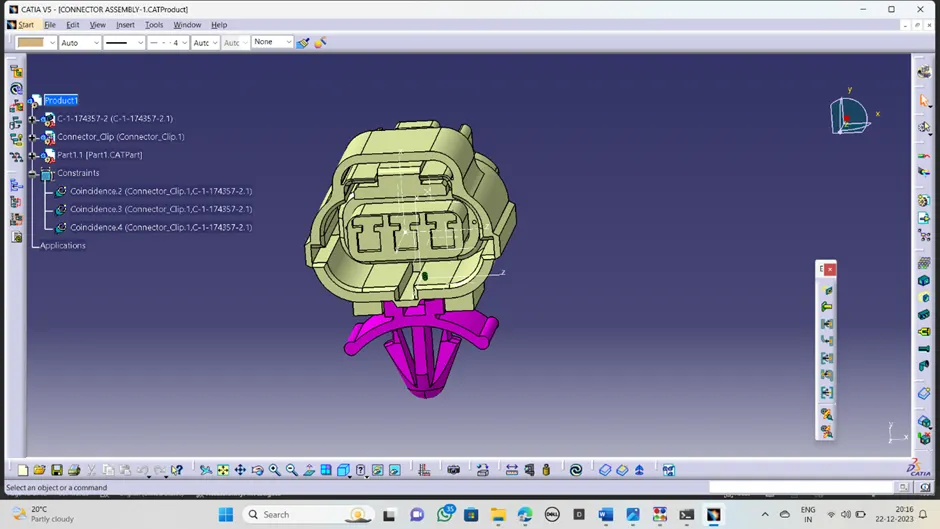
Conclusion:
In this challenge the available 3D cad file was made into the defined electrical connector for using in wiring harness process by using geometrical and electrical parameters and assembly the connector and mounting clip.