Wiring harness design in CATIA V5 - 3D modeling Week 2 Challenge
....
...
Challenge 1
Wiring harness design in CATIA V5 - 3D modeling Week 2 Challenge
AIM: \
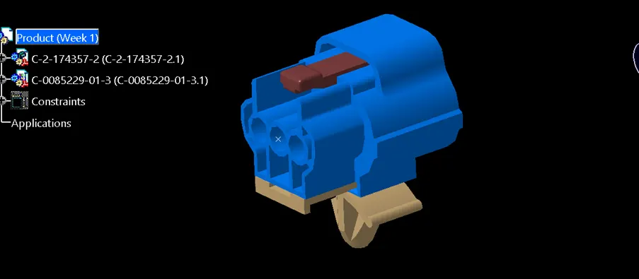
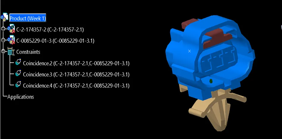
Download following connectors & Connector clip cad data from given link & define it as Electrical Connector using Electrical Part design Workbench. Define all the necessary properties to Connectors & Clip.
- Deutsch DT06 – 08SA ( https://www.te.com/usa-en/product-DT06-08SA.html)
- Tyco 174357-2 (https://www.te.com/usa-en/product-2-174357-2.html?source=header-match)
- Tyco 85229-1 (https://www.te.com/usa-en/product-85229-1.html?q=85229&source=header
INTRODUCTION TO WIRE HARNESS
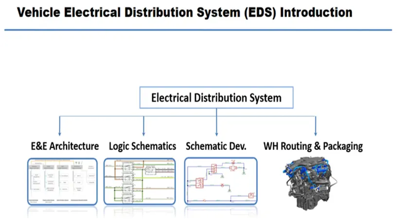
CATIA V5 Wiring Harness Design: An Introduction
CATIA V5 is a powerful 3D design software widely used in various industries, including automotive, aerospace, and shipbuilding. Its Electrical Harness Design module specifically caters to the intricate process of designing and managing complex wiring systems.
What is a Wiring Harness?
Imagine the nervous system of a human body. A wiring harness plays a similar role in machines and vehicles, carrying electrical signals and data between various components. It's a bundle of wires protected by sleeves and connectors, routed strategically to ensure optimal performance and minimize interference.
Why use CATIA V5 for Wiring Harness Design?
CATIA V5 offers a comprehensive set of tools and functionalities for efficient wiring harness design, making it a preferred choice for engineers and designers. Here are some key benefits:
- 3D Visualization: Create and visualize accurate 3D models of the entire harness, including wires, connectors, clamps, and sleeves, facilitating clash detection and ergonomic routing.
- Automated Routing: Leverage intelligent algorithms to automatically route wires through complex geometries, saving time and ensuring optimal paths.
- Bill of Materials (BOM): Generate accurate BOMs automatically, listing all components required for harness fabrication, streamlining procurement and inventory management.
- Digital Mockup (DMU): Integrate the harness design with the overall 3D assembly, enabling interference checks and virtual prototyping for better design validation.
- Collaboration: Facilitate seamless collaboration between design, engineering, and manufacturing teams by providing a shared platform for data visualization and analysis.
Getting Started with CATIA V5 Wiring Harness Design:
CATIA V5 offers dedicated workbenches for electrical harness design, such as Electrical Harness Design and Electrical Assembly Design. These workbenches provide specific tools and commands for managing wires, connectors, clamps, and other harness components.
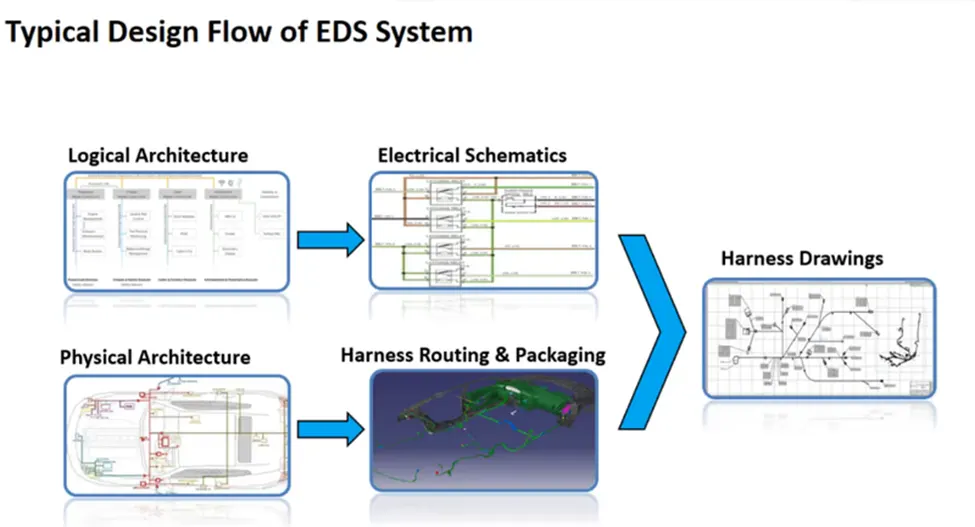
Here's a basic workflow for designing a wiring harness in CATIA V5:
- Define the Electrical Schematic: Create a 2D schematic diagram representing the electrical connections between components.
- Import the 3D Model: Import the 3D model of the assembly where the harness will be installed.
- Place Connectors: Position electrical connectors on the 3D model based on the schematic diagram.
- Route Wires: Use automated or manual routing tools to define the paths for each wire between connectors, considering factors like length, clearances, and bending radius.
- Add Clamps and Sleeves: Place clamps and sleeves strategically to secure and protect the wires along their route.
- Generate BOM and Documentation: Automatically generate a BOM and other necessary documentation for manufacturing and assembly.
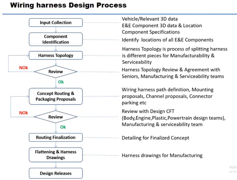
DEFINIG ELECTRIC PARAMETER FLOW CHART
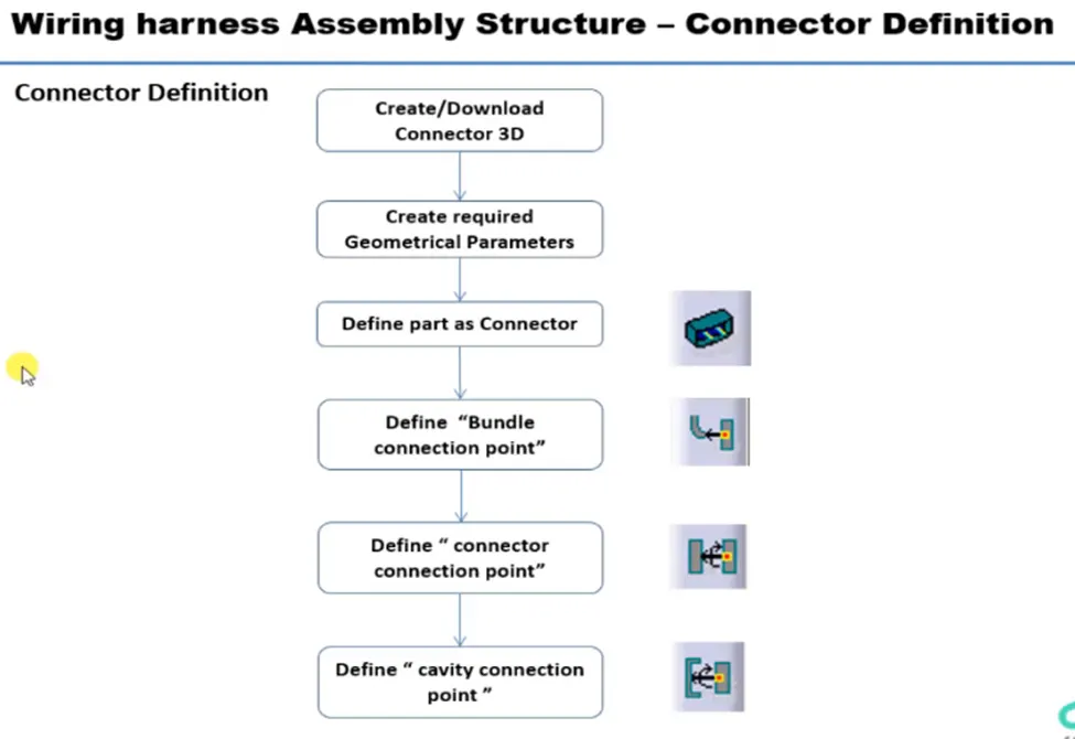
CONNECTOR DEFINATIONS IN CATIA V5
1. Deutsch DT06 – 08SA
Connector connection point:
Create midpoint on the contact face which will be normal to wire bunddle insertion.
Create Axis System with respect to the point which we have created and defining the axis direction as shown below,
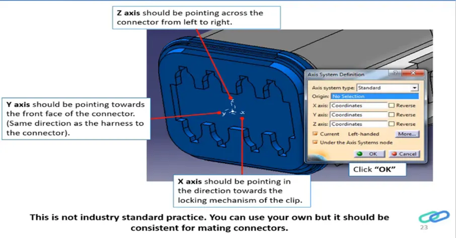
Bundle connection point:
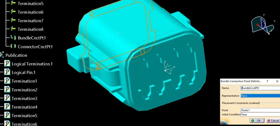
Switch to 'Electric Part Design'
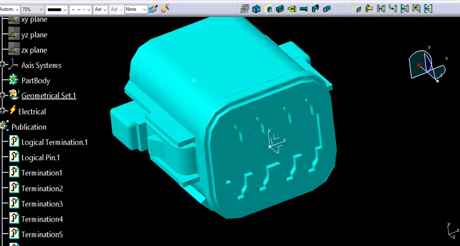
Define the part as connector in catia, give no. of termination as 8 because we have 8 entry points for wire.
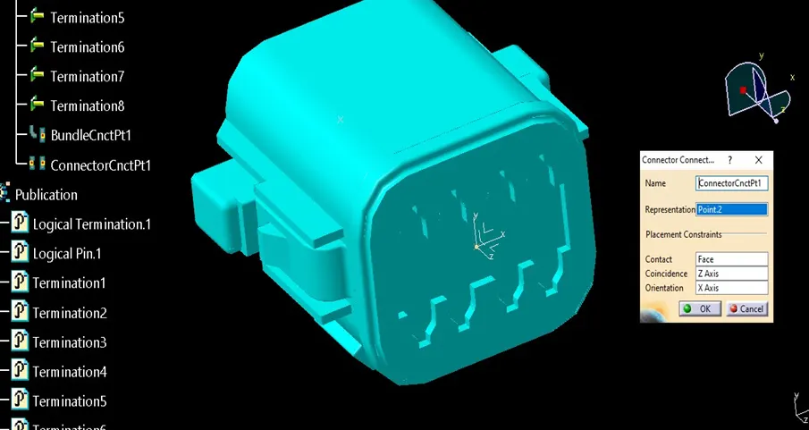
2.Tyco 174357-2
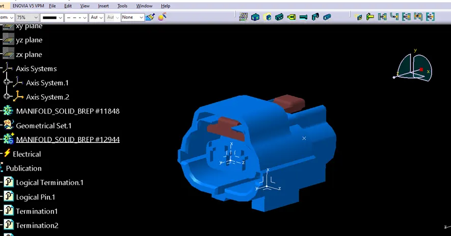
- Create midpoint
- create Connector connection point
- create Connector connection axis system
- create cavity connection point
- create cavity connection axis system
- Switch to Electric part design and define part as connector
- Define Connector connection point and cavity connection point
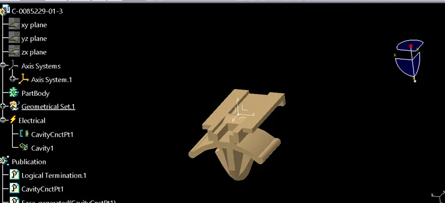
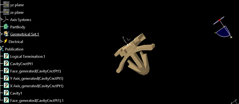
3. Tyco 85229-1
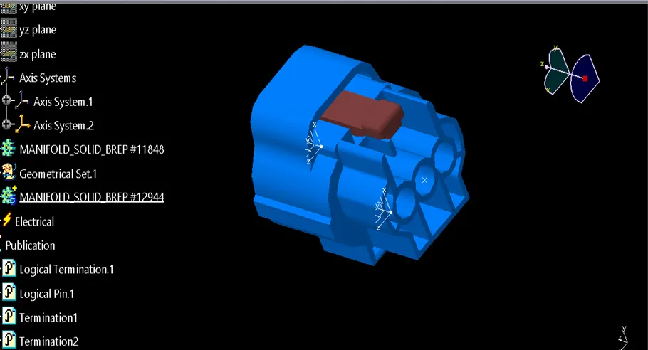
- Create midpoint
- create cavity connection point
- create cavity connection axis system and orientation should be same as in connector
- Switch to Electric part design and define part as Mounting Equipment
- Define cavity connection point
Electric Assembly Design
- Import Connector and cavity / mounting clip.
- Select Defing Eelectric connection
- select cavity and then connector.