Wiring harness design in CATIA V5 - 3D modeling Week 2 Challenge
AIM
To define given CAD files to Electrical Connector using Electrical Part design Workbench and Define all the necessary properties to Connectors & Clip.
CAD Files
- Deutsch DT06 – 08SA
- Tyco 174357-2
- Tyco 85229-1
INTRODUCTION
The wiring harness is the combination of electrical cables, or assembly of wires, that connects all electrical and electronic (E/E) components in the automotive vehicle, like sensors, electronic control units, batteries, and actuators. The wiring harness handles the energy and information flow within the E/E system to fulfill primary car functions, such as steering and braking as well as secondary car functions, such as ventilation and infotainment.
Assembly structure
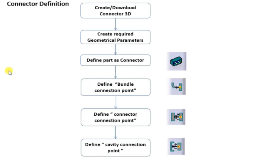
- Connector connection design procedure
Deutsch DT06 – 08SA
- Create midpoint on the contact face which will be normal to wire bunddle insertion.
- After creating points, Create Axis System with respect to the point which is created and defining the axis direction as shown below,
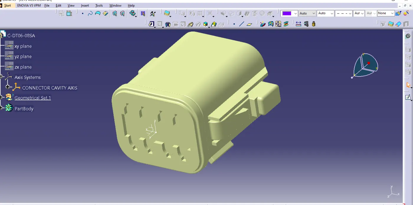
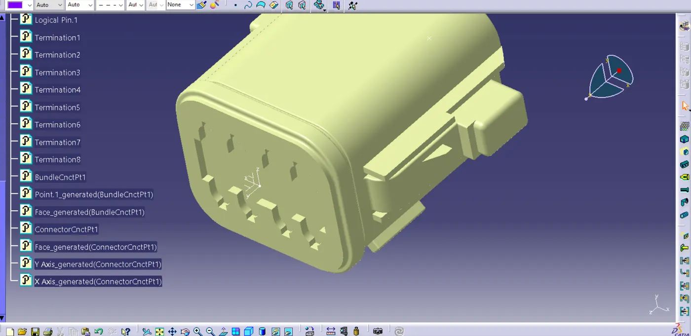
- Now switch to electrical part design module and define part as connector and then Buddle connection as shown below
Tyco 174357-2
- Create Connector connection point.
- Create cavity connection point and axis system.
- Switch to part(Electrical) part design and define it as connector.
- Define connector point and cavity connection point
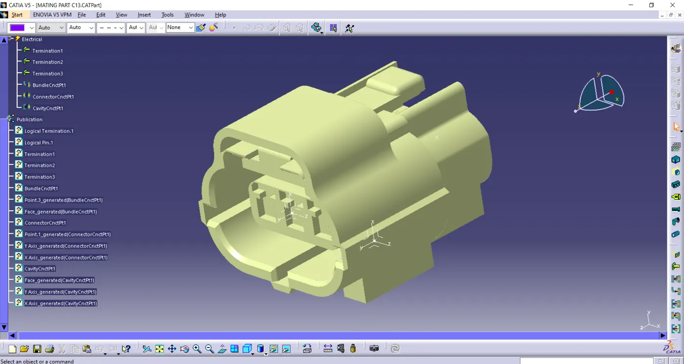
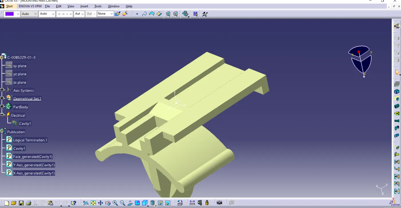
Tyco 85229-1 –
- - create cavity connection point
- - create cavity connection axis system and orientation should be same as in connector
- - Switch to Electric part design and define part as Mounting Equipment
- - Define cavity connection point.
CAD files ATTACHED BELOW