Advanced Sheet Metal Design Using NX Cad Challenge_1_Casing Design
CASING Design
OBJECTIVE:
To learn to design a sheet metal casing by using Siemens NX and write a detailed report on Sheet Metal Component with good explanation on Sheet Metal modelling tools applied throughout the modelling.
INTRODUCTION:
Sheet metal parts are widely used in machinery, enclosure, brackets, and automobile due to its various advantages. Sheet metal is nothing but the thin sheets made from metal of size ranging from 0.5 to 6mm. In this project sheet metal of thickness 1 mm is used.
DESIGN METHODOLOGY:
Flow chart
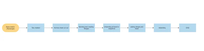
Explaination of tools:
Tab: Use this command to create a base feature by extruding a sketch along a vector by thickness value, or by adding to existing faces & bend regions of a sheet metal part.
Normal cut: This tool is used to cut the material by projecting a sketch onto the model and then cutting normal to the faces intersected by the projection
Bending: Also known as press braking, flanging, die bending, folding and edging, this method is used to deform a material to an angular shape.
Dimple: Dimple is used to give more strength to thr part. The flat portion of the part posses less strength & rigitity. So, there are high chances of failure in the part. The Dimple adds strength & rigidity to the part also reduces the chances of failure.
Bead: Use the bead command to lift material along the contour of a sketch that simulates a stamping tool.
Images of views:
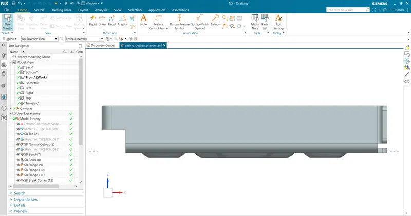
Front View
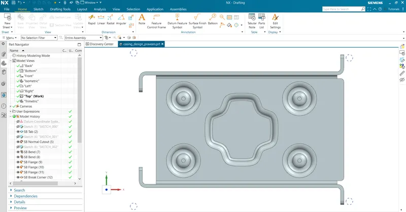
Top View:
Isometric View
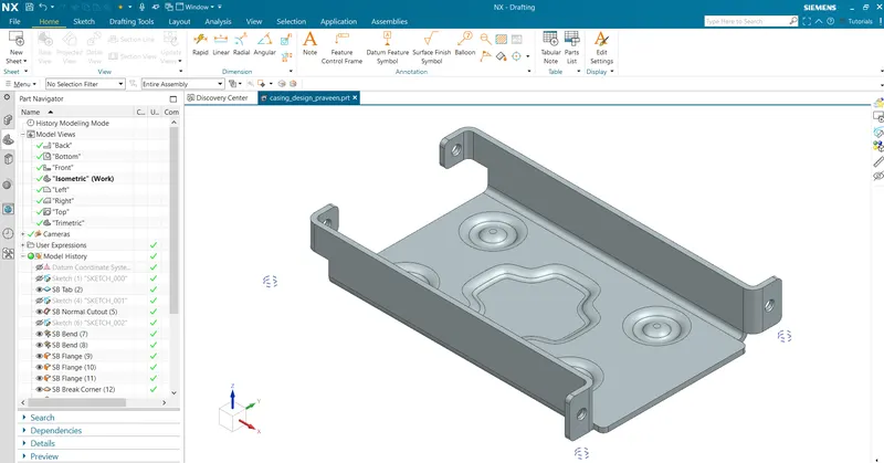
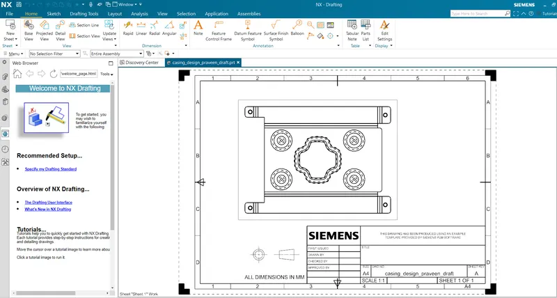
Drafting image