Wiring harness design in CATIA V5 - 3D modeling Week 2 Challenge
WIRING HARNESS DESIGN
Aim:
This project is for study and understand the different models of the connector and the conector clips and covert them innto electrical parts using catia V5.then define all necessary properties and understand the wiring harness design process by creating the requried provisions for connecting them in the assembly workbench.
Introduction:
Wiring Harness:
A wiring Harness is often reffered to as a cable harness or wiring assembly,a systematic and integrated arrangement of cables within a insulated material.the purpose of the assembly os to transmit signal or electric power.cables are bound together with straps,cable ties,cable lacing ,sleeves,electrical tape,conduit or a combinations.The wire harness simplifies the connection to a larger components by integrating into a single unit for drop-in installation.A wiring harness consists of different sets of connectors like terminals and wires which run through the entire vehicle and transmit information.
A wiring Harness process is designed based on the geometric and electrical requirements of the equipment it is to be installed in and once the initial Design is established aschmetic is used to create the manufacturing paperwork and assembly board for the harness.The assembly board is also called as a pin board is a full size diagram of the Harness that shows all of the components and their locations.It also serves as the workbench for the harness.
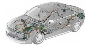
connector:
A Connector is a coupling device that joins electrical terminations to create an electrical circuit.Connectors enable contact between wires,cables,printed circuit boards and electronic components that are engineered to reliably transmit data,power and signals in the hardest environment.It offers to withstand harsh conditions,retentions,emi shielding and reduses application size and power usage while enabling increased performance.
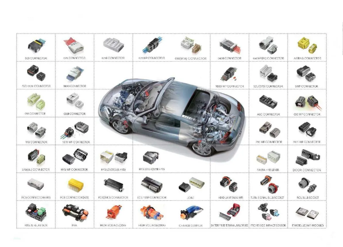
A catalogue is a Catia V5 Document that keeps a list of references to other Catia parts and features.A typical Catia parts and features.A typical CAtia Document is a generic family table with specfic instances within a library context with a //file structure.In pratice,catalogues behave like large assemblies.
Use catalogues to Insert their parts and features into other Catia V5 documents.Catalogues provide the ability to manage and access their part standards in a centralized location,such as windchill.Catalogue are tightly integrated with most of the catia V5 workbenches,including but not limited to assembly Design,Electrical Design,Electrical Harness,and piping Design.
Objective:
- Download the requried part files from the given source link.
- Define the CAD data as electrical connectors using the electrical part workbench.
- Add the eletrically Defined parts to the connector catalogue file for future reference.
- Using electrically Assembly Design workbench,Create assembly of connector housing with the mounting clip.
Design Methodology:
Procedure of the connector for defining it electrically,
- First Download the connectors and mounting Clip from the given link source.
- Get into the mechanical part workbench to create required geometrical parameters.create connector connection point and Bundle connection point on the required sides of the CAD part.
- create axis system on the connector connection point such a way that the Y coordinate facing normal to the connector face x,coordinate facing towards the locking mechanism and z coordinate facing to the top.
- Create cavity connection point for the connectors having the cavity for mounting clips
Using the geometrical parameters created,
- Define part as electrical connector
- Define bundle connection point.
- Define Connector connection point.
- Define cavity connection point.
1.Model 1 Connector (Deutsch DT066-08SA):
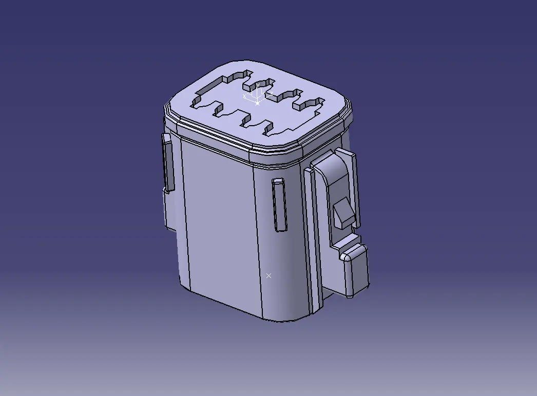
Open one of the connector compatible part and locate the center point of the connector on either side of Bundle Connection point and Connector connection point by selecting the two points on the outermost edge of the each contacting face.Position the axis of the connector connection point with respect to the center point by placing the Y axis towards connecting point direction and the X axis pointing towards the side of the locking mechanism.
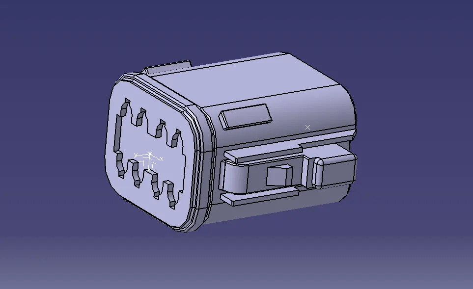
- Now switch to the electrical part Design and add the connector part file into the catalog by opening the newly created catalog in store device option and selecting the family as connectors.
Define the CAD part model as a connector by using the define connector command available in the electrical part Design workbench by giving the apprppriate number of terminal poi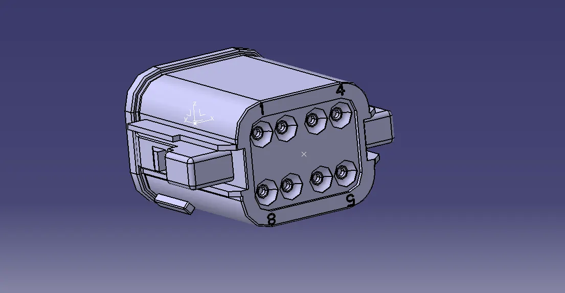
By using the Define bundle connection point command available in the electrical part Design workbench and the created bundle center point define the bundle connection point of connector of compatible part.
The next step is to define the connector connection point by giving the representation as the connection point,selecting the face of contact,coincidence direction as Y axis and orientation direction as x axis.
2.Model 2 Connector (Tyco 174357-2):
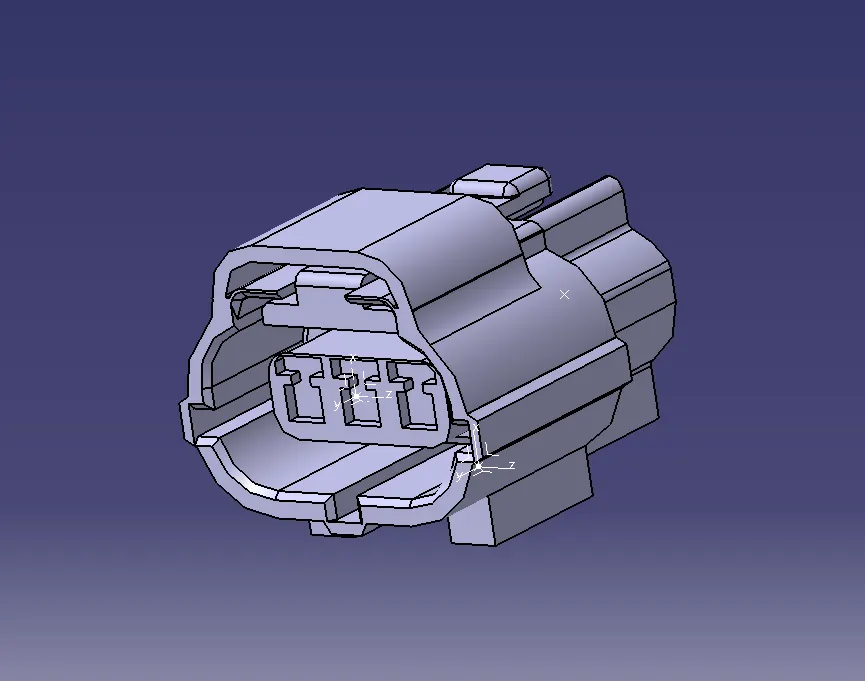
For the Clip mpounted connector compatible part first we need to identify the type of clipping arrangement used for this connector and usderstand the mating face for them.Place the axis system by defining the center point on one edge of the mating face with cavity clip and the axis direction should be the same as the axis direction given for the connector connection point.
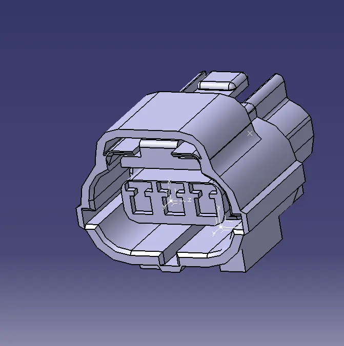
- Now switch to the electrical part design and add the connector part file into the catalog by opening the newly created catalog in store device option and selecting the family as connectors.
- Define the Cad part model as a connector by using the define connector command available in the electrical part desiign workbench by giving the appropriate number of terminals.
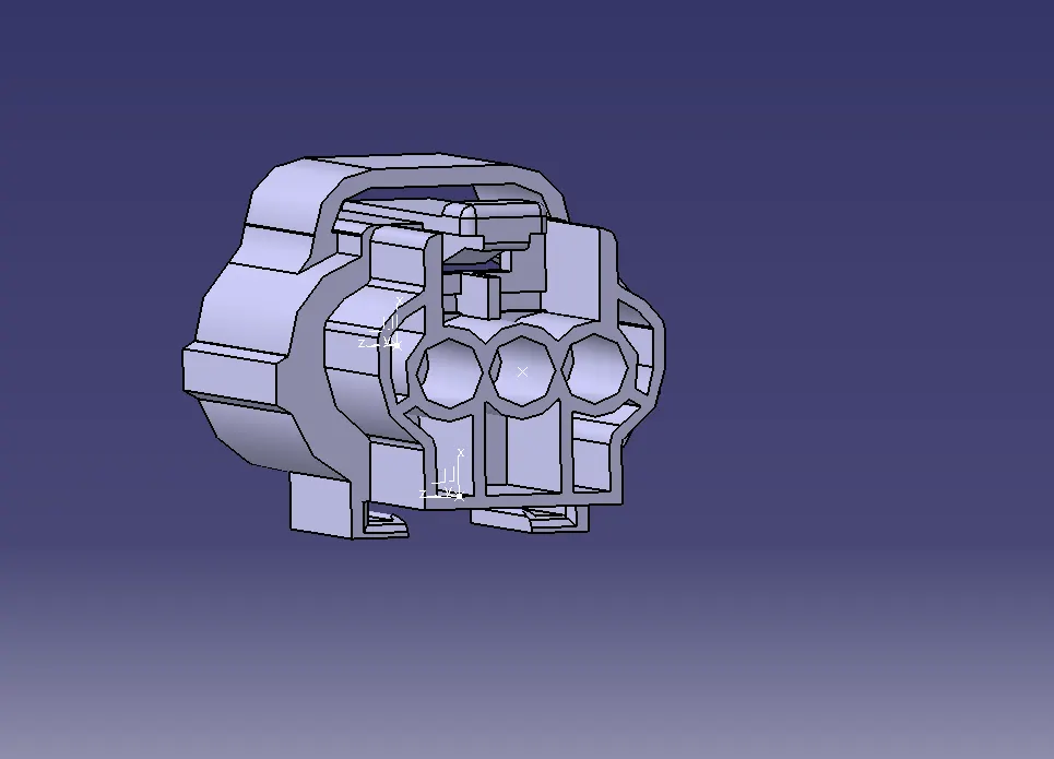
By using the Define bundle connection point command available in the electrical part Design workbench and by selecting the face of bundle entry side and the created bundle center point define the bundle connection point of connector compatible part.
The next step is to Define the connector connection point by giving the representation as the connection point,Selecting the face of contact ,coincidence direction as Y axis and orientation direction as x axis.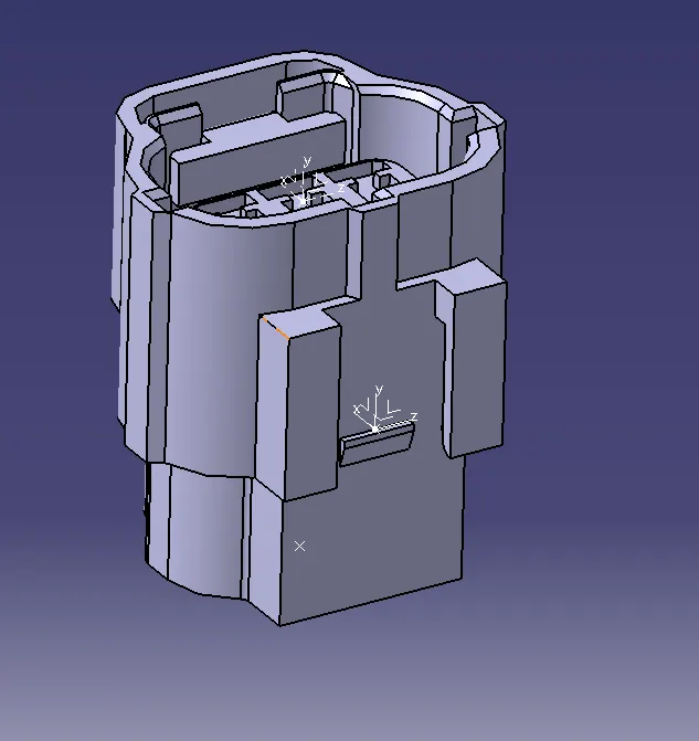
For the compatible part having cavity clip arrangement we have to define the cavity connection point by defining the representation,contact face,coincidence axis and orientation direction by selecting the representation as cavity clip point,the face of the contact of the cavity clip,coincidence direction as y axis and orientation direction as x axis.
3.Model 3 Connector clip (Tyco 85229-1):
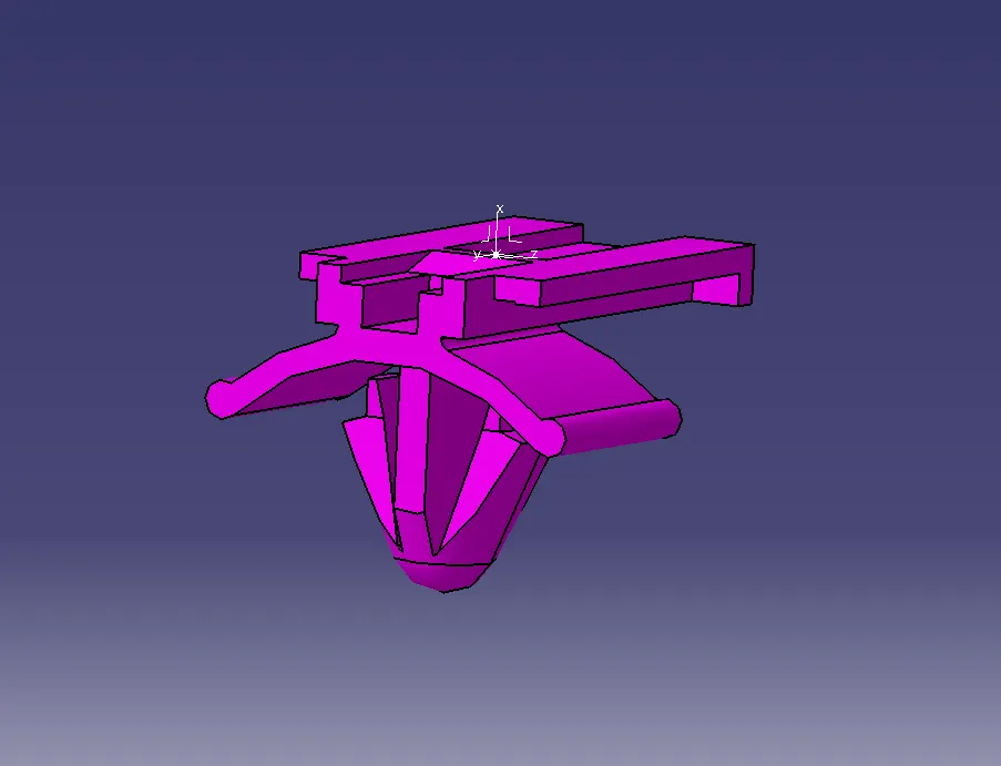
Connector Clip is then opened in the cad part file and creates the center point and axis system with respect to the compatible part having cavity clip arrangement and the locking mechanism.
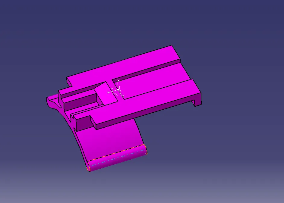
The cavity clip part model is first defined as mounting equipment by using the define mounnting equipment tool and by selecting the define cavity tool it will have defined as a cavity.and finally electrical cavity also done.
Electrical Assembly Workbench:
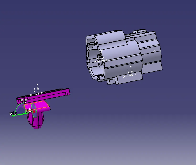
Open the elctrical assembly design workbench by copying and pasting them or by adding the existing component command available in the insert toolbar.
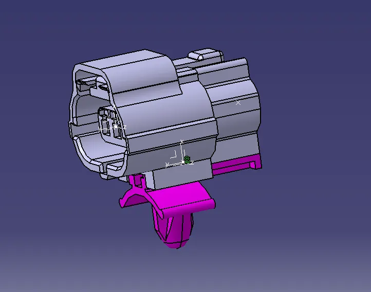
By using connect electrical Devices tool we can join them together by adjusting them into the apprppriate location.Here the given connector parts are not compatible with each other so we have assembled the cavity clip and one part of the compatible connector.
Conclusion:
The given connectors and mounting clip are defined as electrical parts with the help of required geometrical parameters and assembled together.Also connectors ar eadded to the catalog file for the future reference and use.