Wiring harness design in CATIA V5 - 3D modeling Week 2 Challenge
Wiring harness design in CATIA V5 - 3D modeling Week 2 Challenge
Introduction Wire Harness:
A cable harness, also known as a wire harness, wiring harness, cable assembly, wiring assembly or wiring loom, is an assembly of electrical cables or wires which transmit signals or electrical power.[1] The cables are bound together by a durable material such as rubber, vinyl, electrical tape, conduit, a weave of extruded string, or a combination thereof.
Commonly used in automobiles, as well as construction machinery, cable harnesses provide several advantages over loose wires and cables. For example, many aircraft, automobiles and spacecraft.
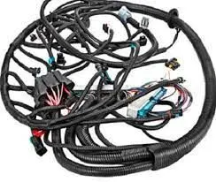
(Wire Harness image)
The wiring harness is the combination of electrical cables, or assembly of wires, that connects all electrical and electronic (E/E) components in the automotive vehicle, like sensors, electronic control units, batteries, and actuators. The wiring harness handles the energy and information flow within the E/E system to fulfill primary car functions, such as steering and braking as well as secondary car functions, such as ventilation and infotainment.
Constructions:
The specific process of vehicle wiring harness design involves the following steps:
- First, the electrical system engineer provides the functions of the entire electrical system, including the electrical load and related unique requirements. The state of the electrical equipment, the installation location, and the form of connection between the wiring harness and the electrical equipment are all key considerations
- From the electrical functions and requirements provided by the electrical system engineer, the complete vehicle electrical schematic is created by adding components required for a function and connecting them together. The functions which are commonly used across multiple vehicles in an architecture platform are stored together.
- After the schematic is defined, the wiring harness design is created. In one platform, the end customers can have a variety of requirements. It is very time-consuming and expensive if different designs are created for each end user’s requirements separately. So, the designer takes care of the multiple variants while designing the wiring harness.
- At the end, a 2D representation of all the wiring designs is created to show the way different wires are bundled and how the bundles are covered to secure the wires. End connectors are also shown in this 2D diagram.
- These designs can interact with 3D tools for the import and export of details. The wire lengths can be imported from the 3D tool and the end-to-end connection details are exported from the wiring harness tool to a 3D tool. The 3D tool uses these data to add passive components such as straps, cable ties, cable lacing, sleeves, electrical tape, and conduits in relevant locations and send them back to the wiring harness tool.
After the design is completed in software, the wire harness is manufactured in the manufacturing plant starting from the cutting area then the pre-assembly area, and finally in the assembly area.
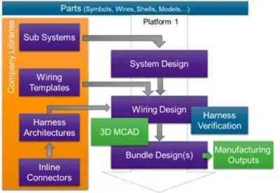
- Better Data Consistency. Tools and methods are created in such a way that they support platform-driven design generation to ensure data consistency and sufficient reuse throughout the flow to impact time to market. This can be achieved by top-down connected design flow and correct-by-construction integration.
- Data Integrity. All functions are built together and designed together to ensure there is no lack of integration leading to design quality problems. This can be achieved by one design database and option handling and a multi-user environment for concurrent design.
- Design Validation. Simulation can be integrated at all levels for sizing and robustness to ensure problems and errors can be found during the design stage itself by built-in simulators for advanced verification and automation for rapid setup and reuse.
Types of Wire Harness Components:
There are several types of wire harness components, each of which is available in multiple variations to suit different applications. These components include:
- Wire: The wire carries the current or signal that powers a device. The wire’s capacity needs to meet or exceed the voltage or bandwidth it’s expected to transmit. Most wires are copper and can have a specially chosen coating.
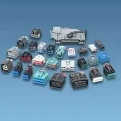
- Connectors: Wire connectors are available in several varieties and sizes to connect different types of wires. While they are usually plastic they can be made from a variety of elements including metal and ceramic.
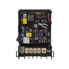
- Fuses: Fuses stop surges of power from overloading or damaging devices on the receiving side of the fuse. Different harnesses use different classes of fuses. They are generally rated for 32 volts or less and vary based on their amperage rating.
- Grommets: Grommets are insulators to keep moisture out of the connector. A grommet can be attached with the terminal or can be a part of the connector.
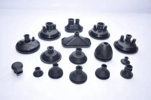
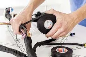
- Outer coverings/Insulators: Also referred to as tubes and sleeves, insulators provide some degree of abrasion resistance, environmental protection, and protection from electrical shock. They can be made of various materials such as nylon or polyolefin.
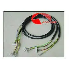
- Relays: Relays turn higher amperage circuits on or off. This quality allows harnesses to power multiple things. Like fuses, they vary based on amperage requirements.
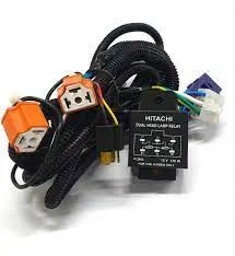
- Strain Relief: Usually added to the outside of the connector. It is designed to prevent the force of pulling of the wires in the connector which could allow the terminal to pull out of the connector making a bad connection. Strain relief can also be added at extreme bend radius which again can put undue force on wire and the terminal inside of the connector.
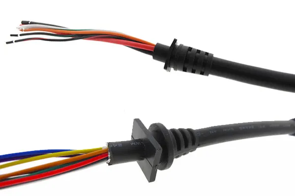
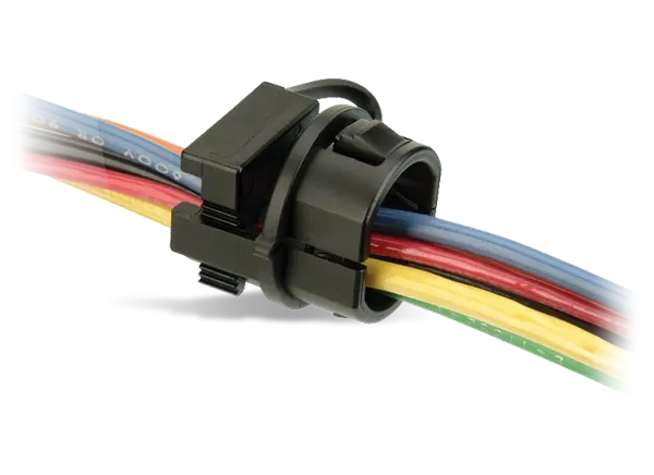
- Terminals: Terminals are the metal parts that are attached to the end of the wire to be inserted into the connector or to be attached to a point on the connecting equipment.
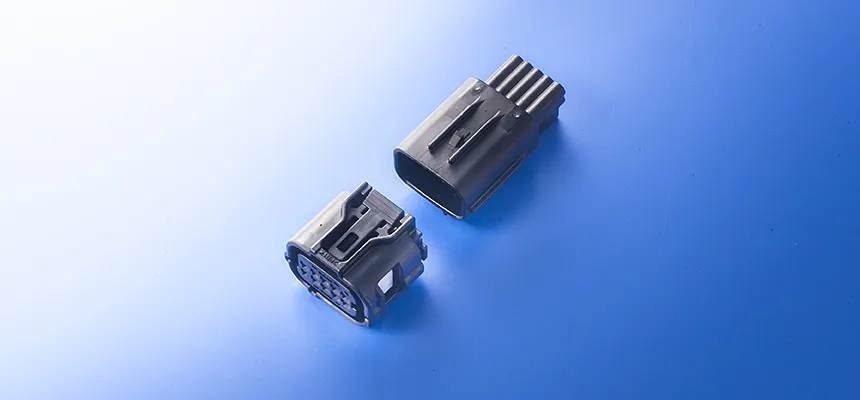
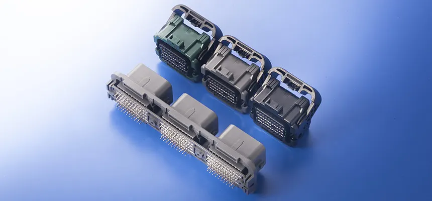
- Ties: Cable ties and clamps keep the wires inside of the harness attached to from a stream of wires to a particular direction. It can also be used to attach to a structure at fixed points to minimize movement.

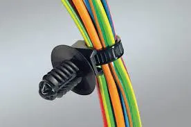
- Locks: Locks are inserted into the connector to prevent the terminal attached to the wire from being pulled out of the connector. It can also assure complete insertion of the terminal into the connector.
Q1. Download following connectors & Connector clip cad data from given link & define it as Electrical Connector using Electrical Part design Workbench. Define all the necessary properties to Connectors & Clip.
Ans) As given in question one i am download the connectors & connector clip cad file from given link and define it as electrical connector using electrical part design workbench.
Below are the images of defined as Electrical Connector and clip.
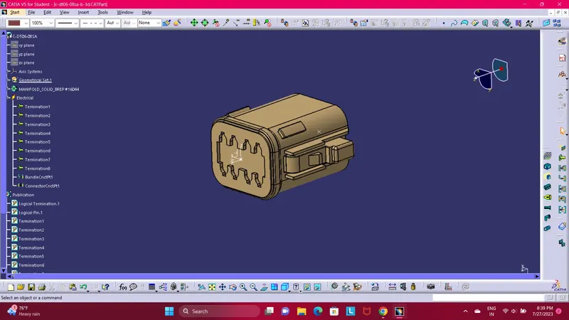
Male Connector (C-DT06-08SA)
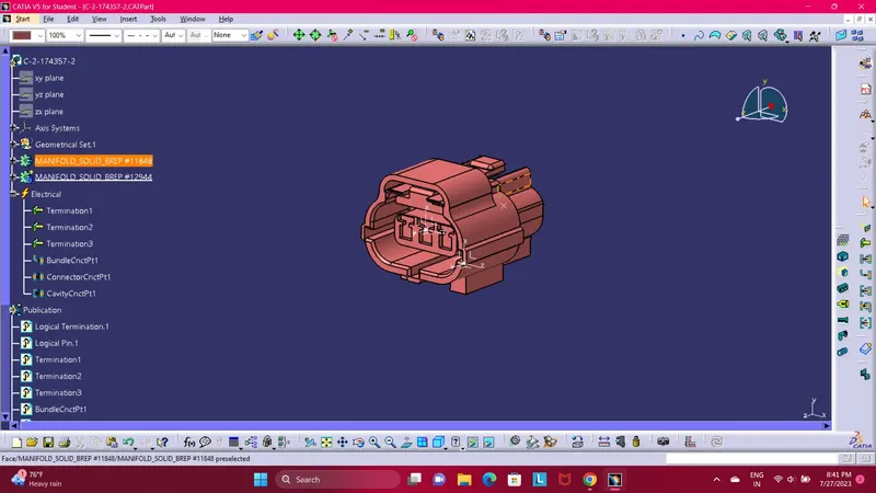
Female Connector (C-2-174357-2)
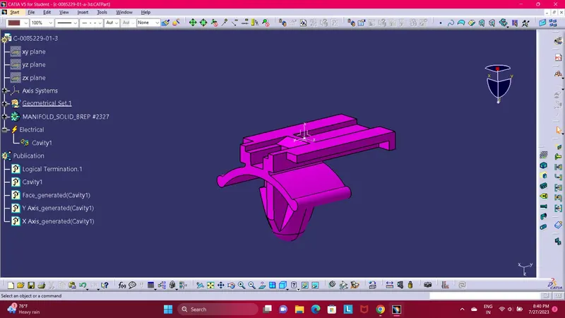
Mounting Clip (C-0085229-01-3)
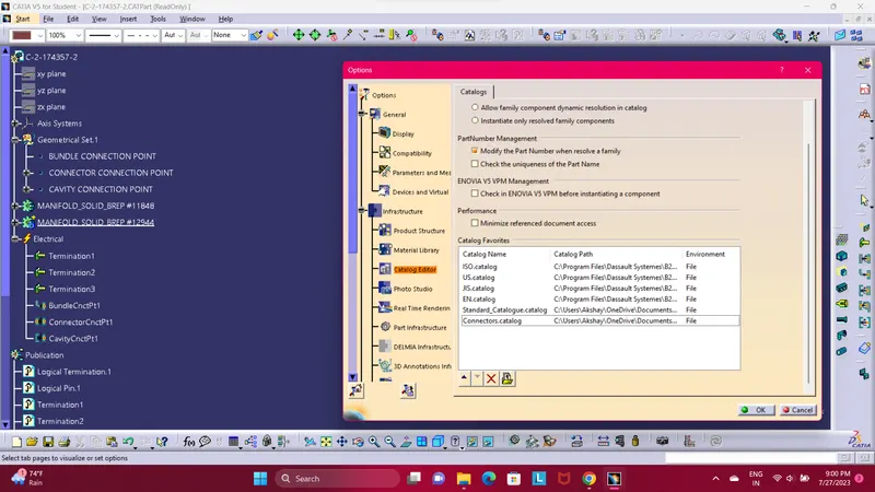
Catalogue creation for Connector