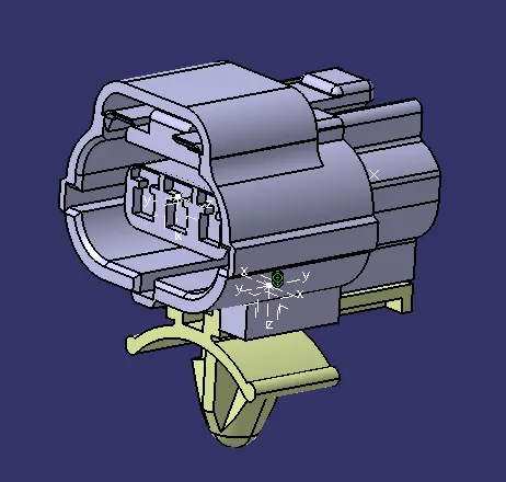
Wiring harness design in CATIA V5 - 3D modeling Week 2 Challenge
1.DEFINING ELECTRICAL COMPONENT
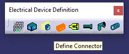
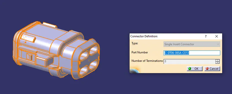
To define the connecter and equipment the specific Toolbox Icon available in Electrical Part Design Workbench used as shown below.
In this Electrical Part Design [EPD] workbench the Electrical Harness assembly component gets defined as electrical components.
2.CREATION OF POINTS
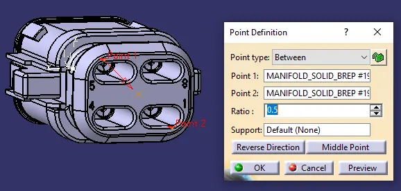
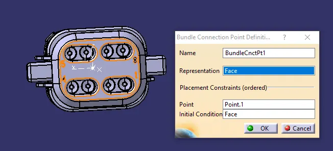
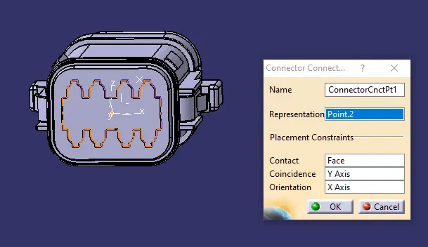
Points are created between two points in the Connector and Bundle Side. The points created have to be in the middle of the surface [approx].
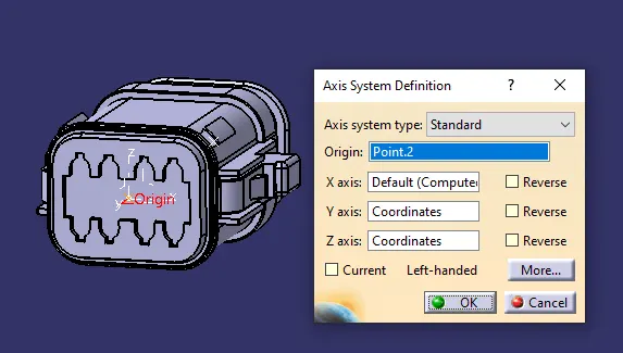
3.ORIENTATION OF THE AXIS
X AXIS- Towards the locking mechanism
Y AXIS- Normal to the surface
Z AXIS- Can be either up or down depending upon the orientation of other two axis [fixed].
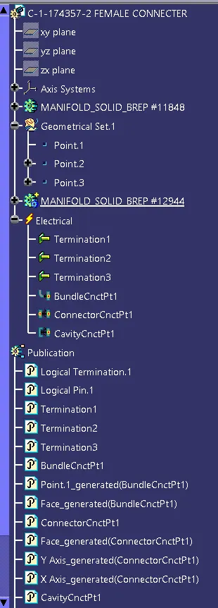
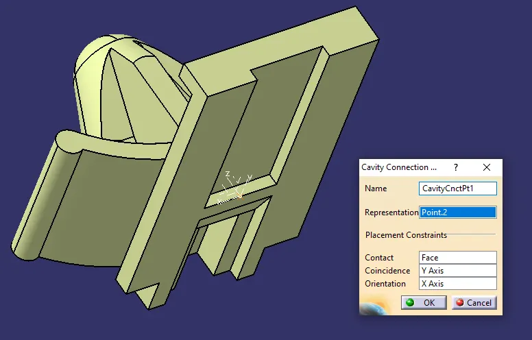
4. CAVITY CONNECTION POINT
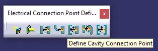
A cavity is defined after generating a point on the surface that needs to be coincided with the face of other electrical component. An axis is created on that point which follows the same rule as point 3 above.
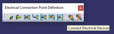
The cavity on both the components are connected using the tool available in Electrical Assembly Design [EAD] as shown below
ELE.PART 1
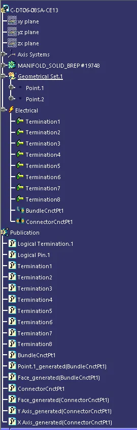
Defining the component
Generating the Points on Connector and Bundle Side
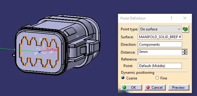
Generating the Axis
Defining Connector Connection and Bundle Connection Point
ELE.PART-2
Defining the component
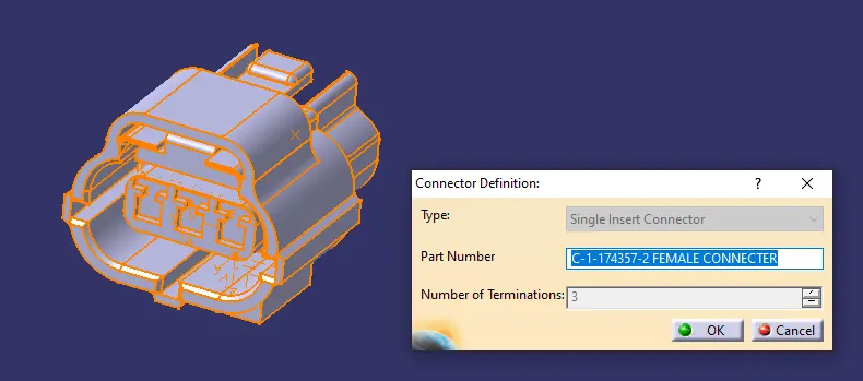
Generating the Points on Connector and Bundle Side
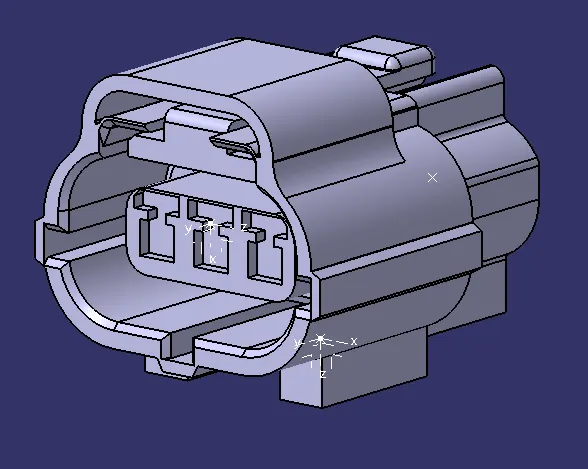
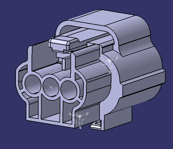
Generating the Axis
Defining Connector Connection and Bundle Connection Point
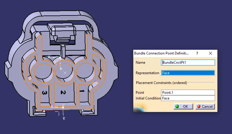
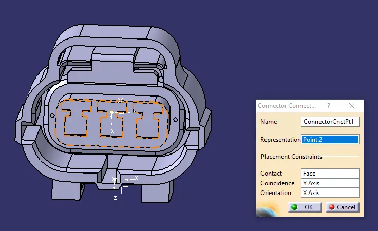
Defining Cavity Connection Point
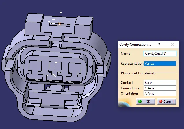
ELE.PART 3
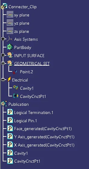
Defining the Cavity and Generating the Axis
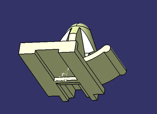
Defining Cavity Connection Point
ASSEMBLING IN ELECTRICAL ASSEMBLY DESIGN