Wiring harness design in CATIA V5 - 3D modeling Week 2 Challenge
Electrical Wiring Harness:
Before Start the work we are doing modified basic settings they are go to TOOLS - OPTION and click on Infrstructure pick on Cache management and click on chach activation and cache size and say ok. And go cataloge editor pick on required option then add on standard catalogue file .we want to standard catalogue file go file - new - catalogue document- fix the location and enter name then say ok.The standard catalogue file have created .
Next move on pick the part inferstructure pick on required option then say ok next go to Equipment and system - select electrical mapping and add the connector files.before we want to have create connector catalogue file is same method on standard catalogue file creation.
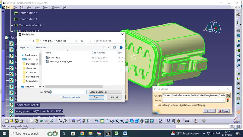
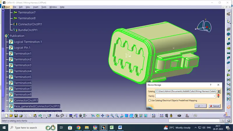
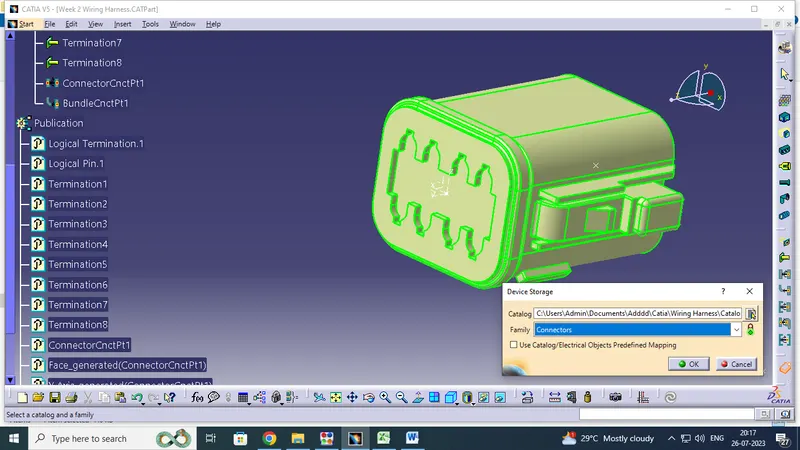
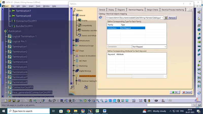
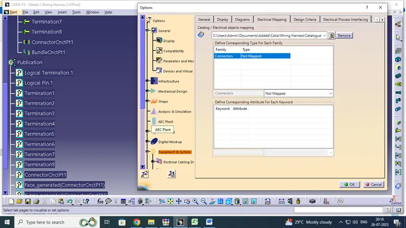
Download the connector in TE.COM then cad file save on electrical part design work bench to get modified on identify the what is connector connectivity point ,what is bundle connectivity point then what is defie cavity and cavity connectivity point with the help on point and axis. then go to pick store device option and save the connector catalogue file.finally i will added on electrical mapping option. why we are saved on this option once we were save this next we want this component part easily to get it .
Open the connector files save on cad file folder in wiring harness location.
1. Deutsch DT06 – 08SA Electrical Female Connector Device
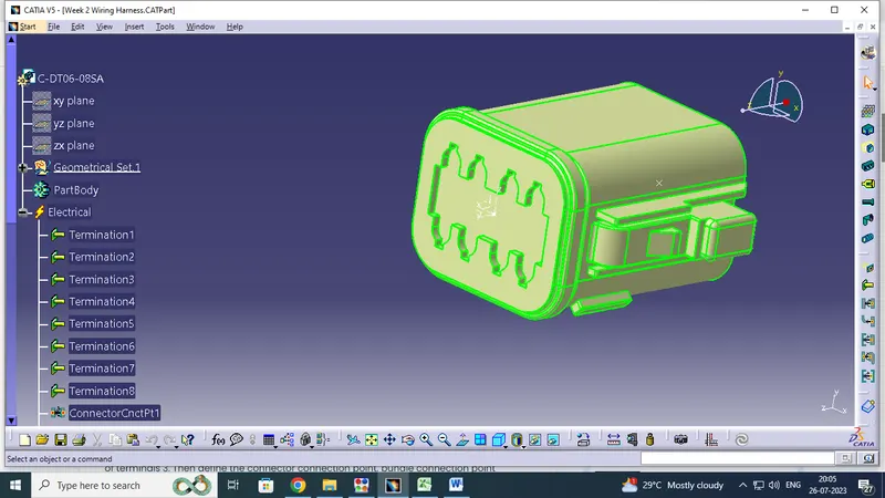
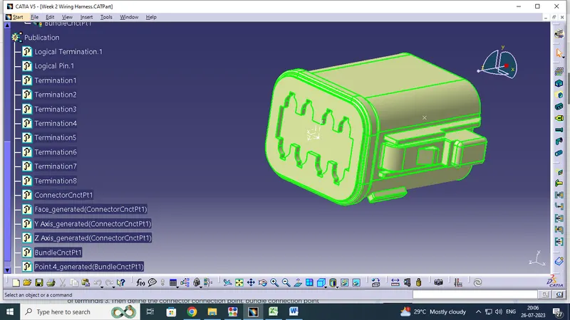
First of all Download the component on TE.COM and open on catia v5 window .Identify the what is connecter connectivity and bundle connectivity .next creat the point and axis in mounting direction.like y axis direction is coinsidence ,z axis is orientation and x axis is side facing.
Select on define connector option and enter the type is single insert connector , Number of terminition - 8 and ok. next pick on connector connectivity point and give requied detailes like ,representing point - mid point of axis ,contact - face , y - direction is coinsidence ,z- direction is orientation and ok .at same time open on Bundle connection point give the representation side ,point ,Initial condition and say ok.
2.Tyco 174357-2 Electrical Connector Device
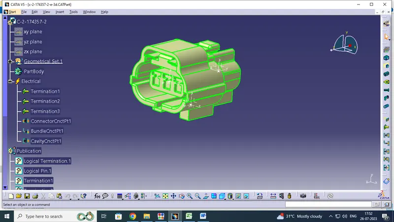
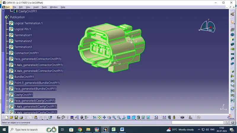
Same Procudure are doing ,Identify the connecter connectivity and bundle connectivity and cavity connector also .next creat the point and axis in mounting direction.like y axis direction is coinsidence ,x axis is orientation and z axis is side facing.
Select on define connector option and enter the type - single insert connector , Number of terminition - 3 and say ok. next pick on connector connectivity poi nt and give requied detailes like ,representing point ,contact , y - direction - coinsidence , X - direction Is oriendation and ok ,at same time open on Bundle connection point give the representation side - face ,point ,Initial condition - face and say ok.
Finally we have to creact on cavity connection point and it same process like Bundle connector point .the deatils are representation side - face ,point - mid point on that surface ,Initial condition - face and say ok.
3.Tyco 85229-1 Cavity Clip
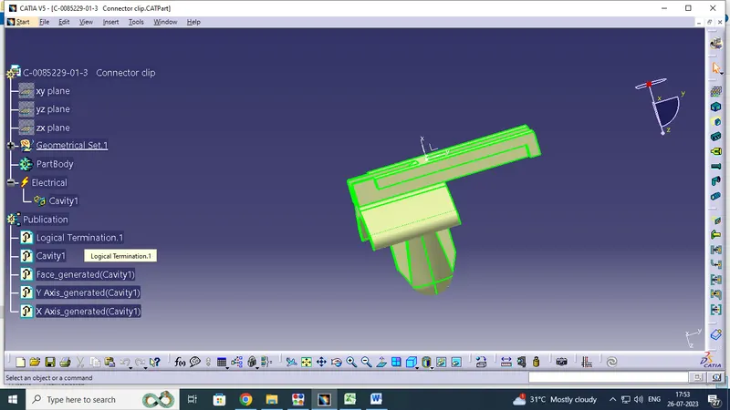
This Component are designed by connect to the connector by using define cavity option . pick on cavity connection point and give requied detailes like ,representing point is mid on Axis point ,contact is mounting face , y - direction - coinsidence its mounting direction , X - direction Is oriendation z direction is side face and say ok ,at same time open on Bundle connection point give the representation side - face ,point ,Initial condition - face and say ok.its is cavity connection point creation .
Assemble the Electrical connector Device and cavity clip:
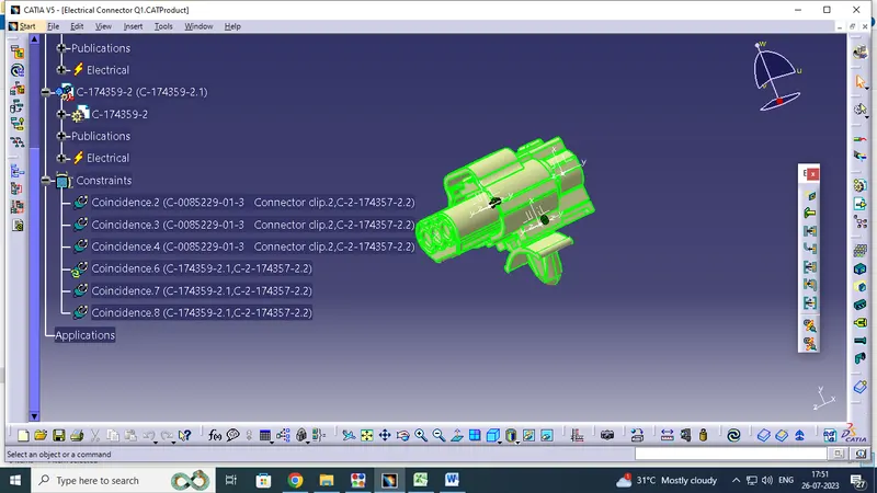
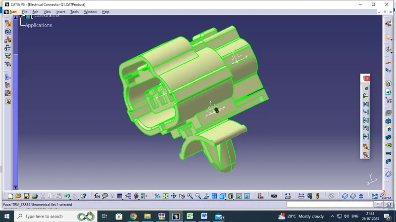
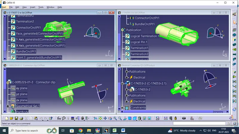
Open on Assemble Design (product ) Work bench window copy the electrical component design parts like connector head male /female and cavity clip past the product window then change the electrical assembly workbench select the connect electrical device option and pick on the cavity clip and connector head point and same process doing on male and female connector devices.