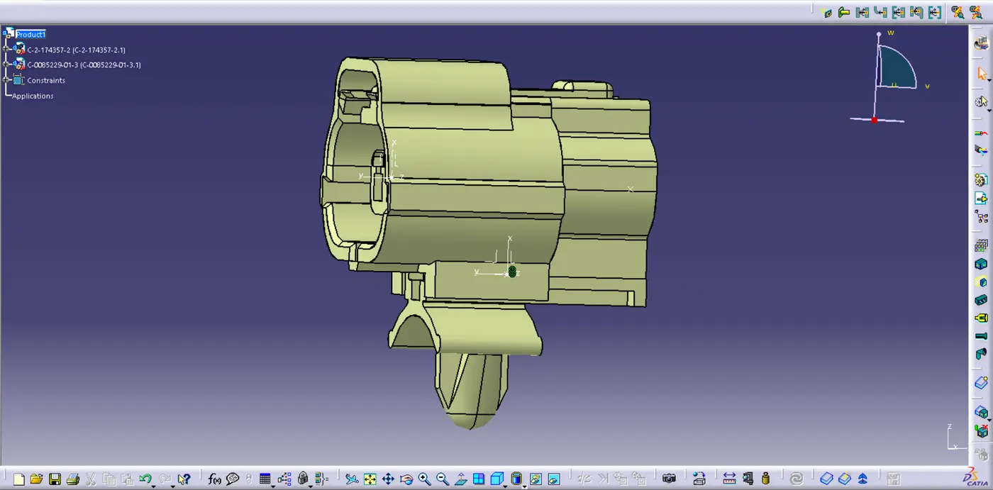
Wiring harness design in CATIA V5 - 3D modeling Week 2 Challenge
1. Deutsch DT06 – 08SA
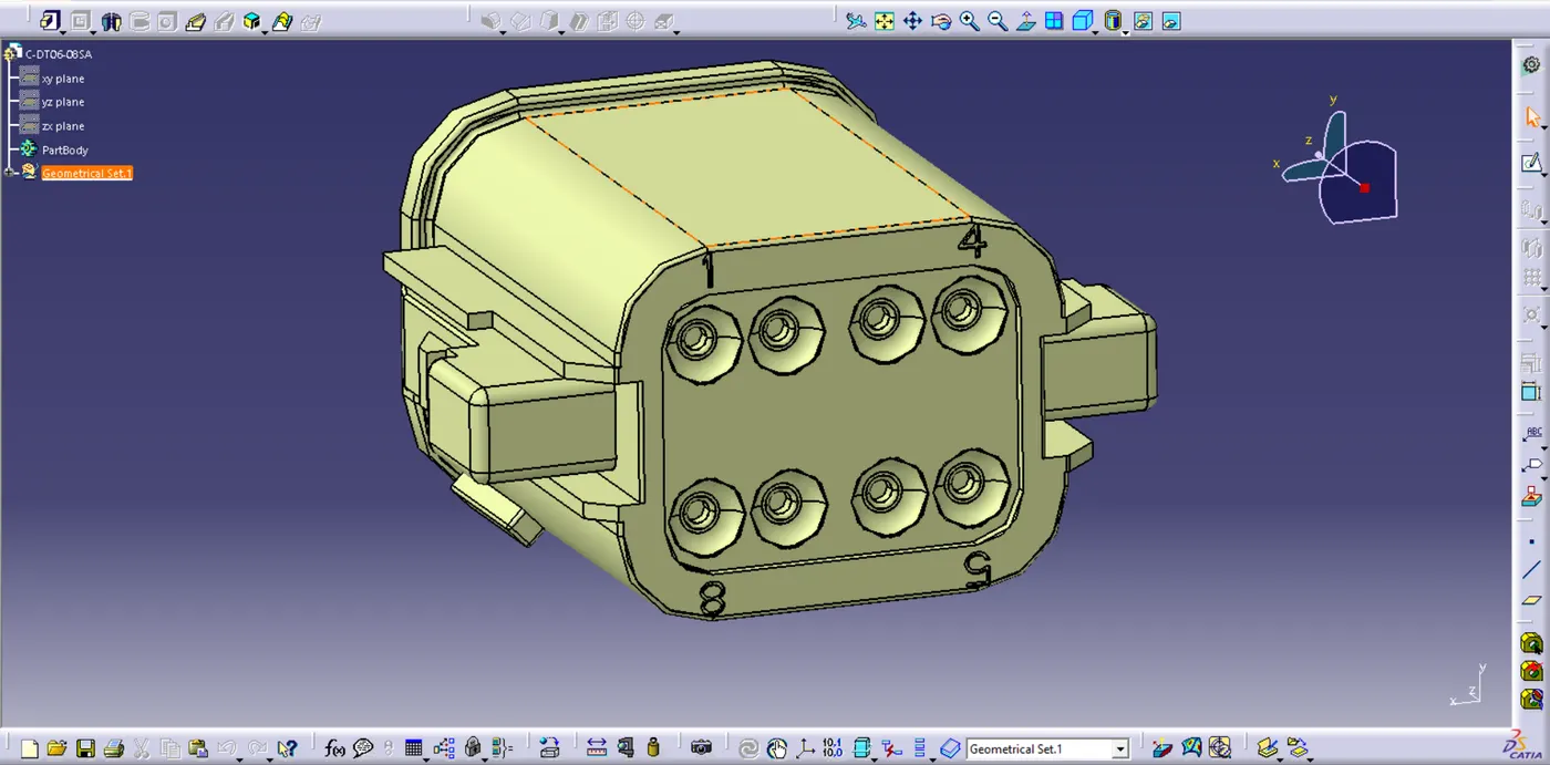
Above Image Shows the Part Body Of our 1st Clip - Deutsch DT06 – 08SA
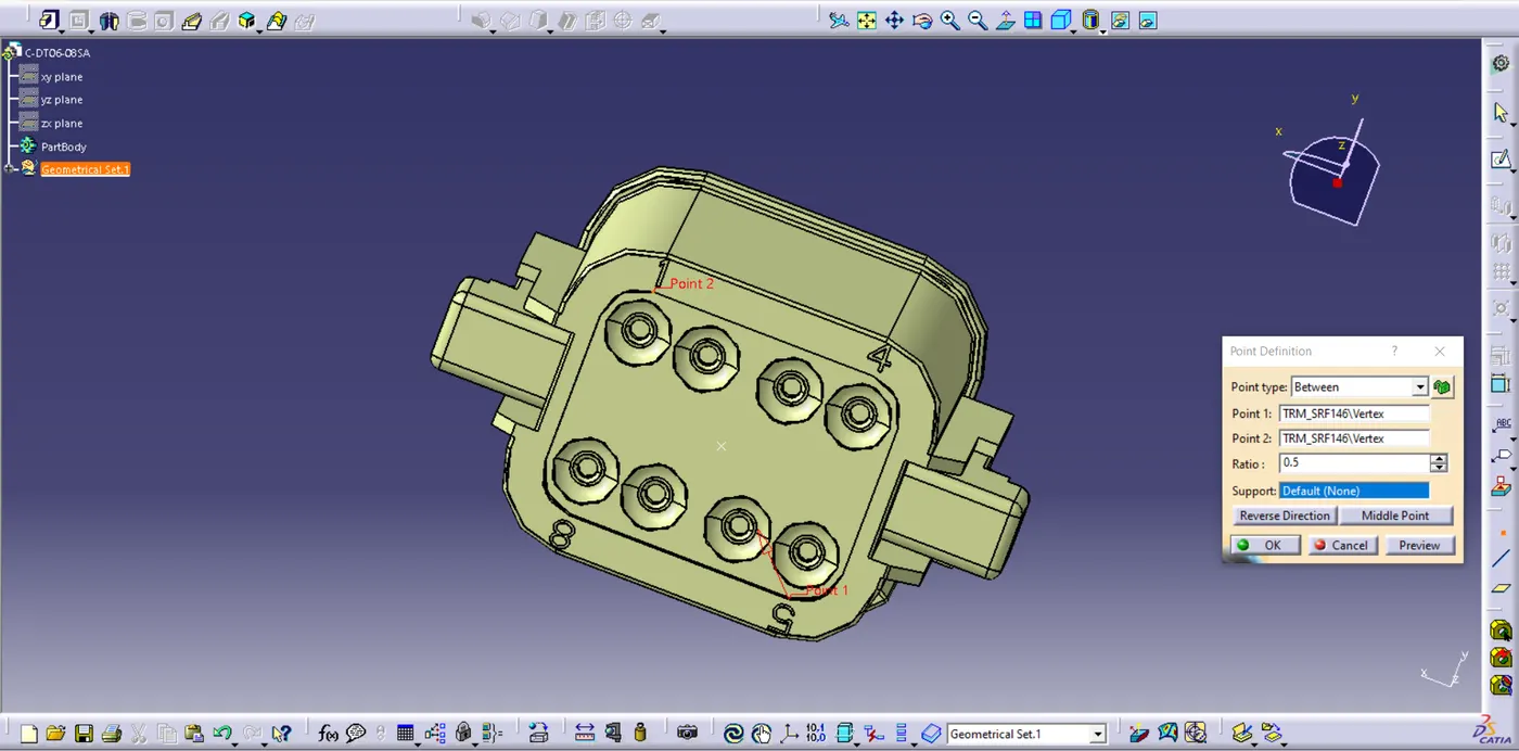
Created a center point on the bundle side using point tool and selecting between option by selecting two point and middle point option.
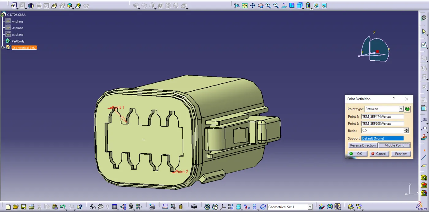
Same for the connector side.

Now, On the connector side created axis system using axis tool and rotating 90deg along x-axis.
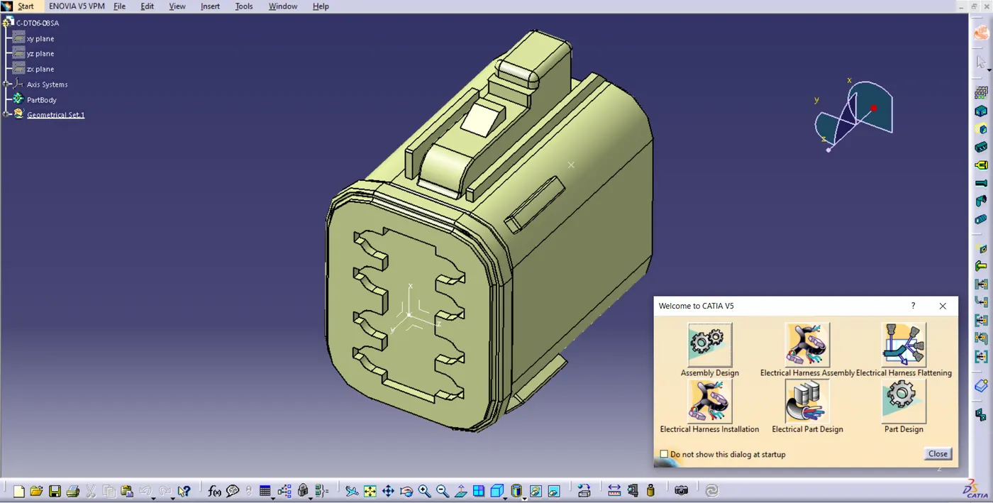
After Creating the axis, Started the Electrical Part Design.
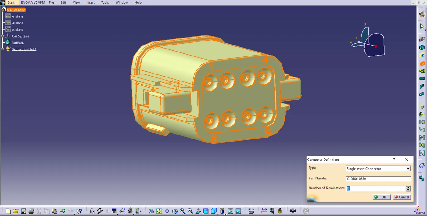
Define the Connector Definiton by entering the Number of Termination - 8
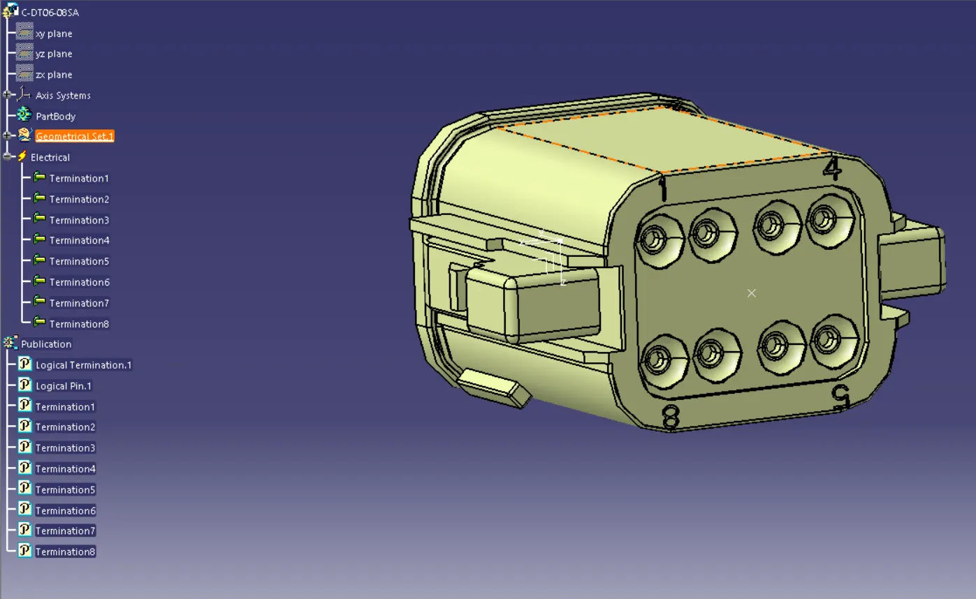
All Created Termination are shown in above Figure
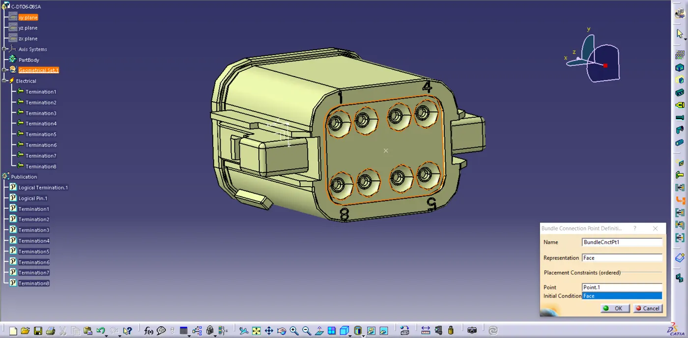
In the above figure, Defining the bundle connection point.
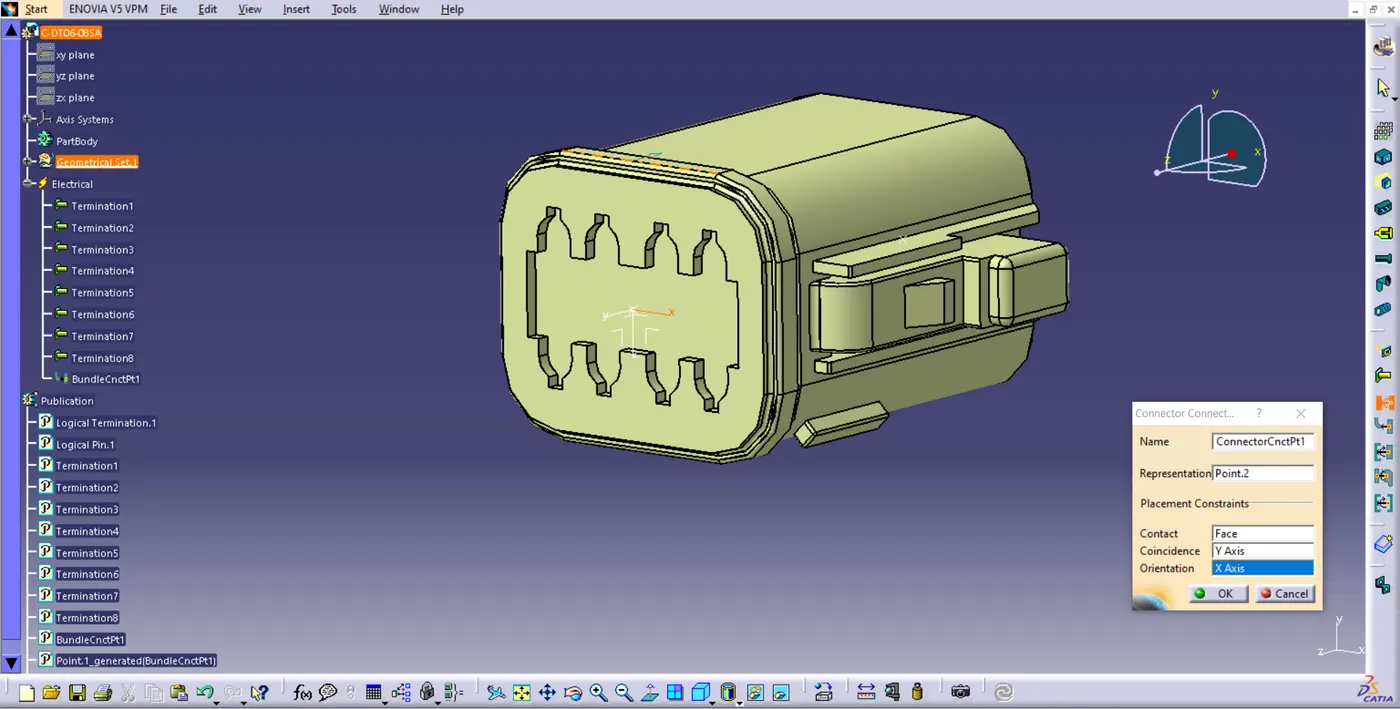
In the above figure, Connector Connection is defiened.
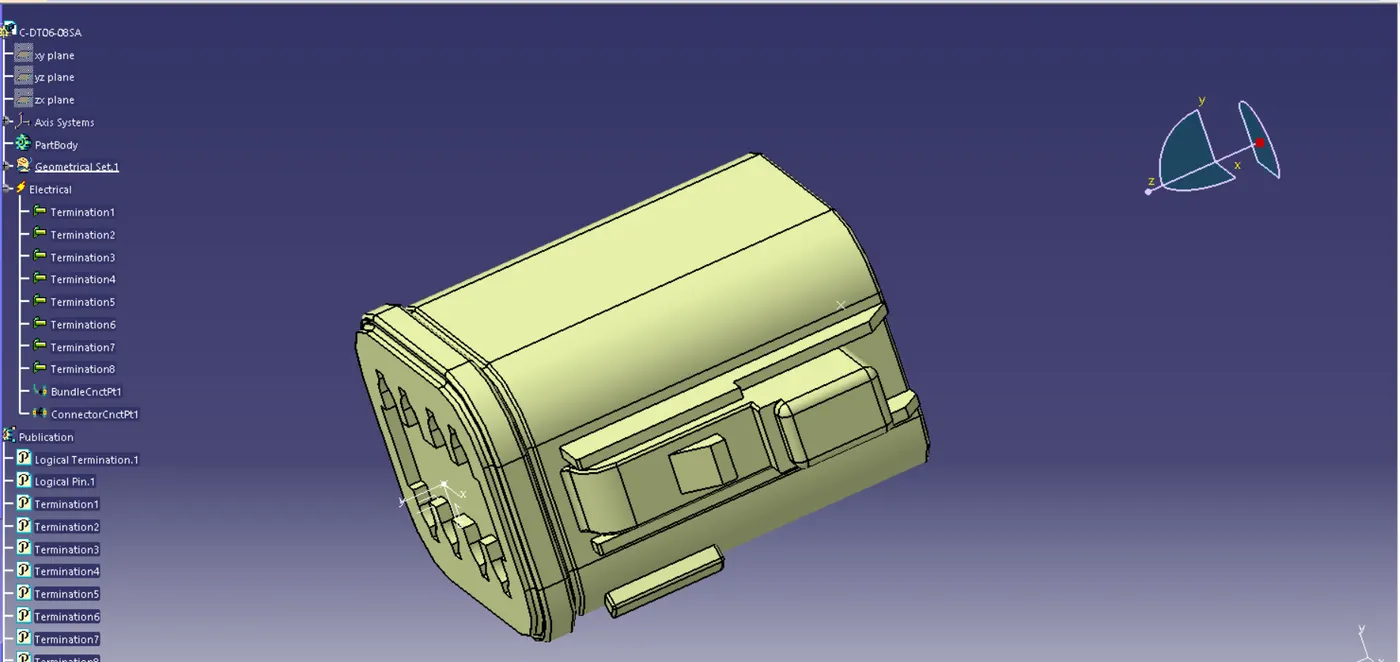
Hence, Our Electrical Connector is Defined Completely.
2. Tyco 174357-2
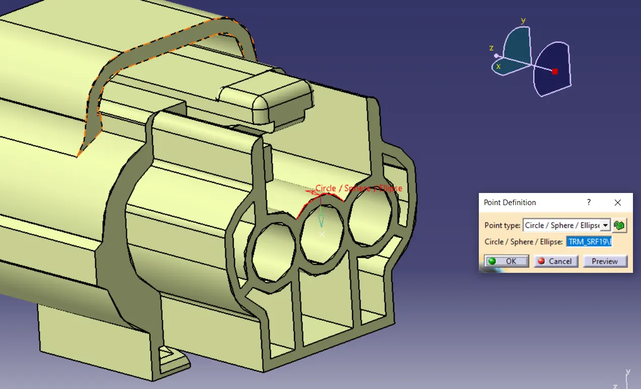
Creteated a center point using point tool and point type as circle / sphere / Ellipse on the Bundle Side.
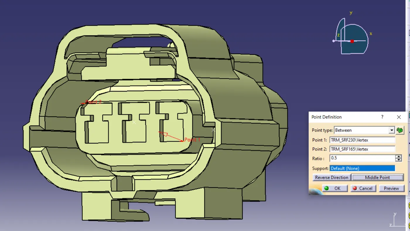
Similarly Created point on the Connector side using point tool and point type as between and selecting two points and defining as middle point.
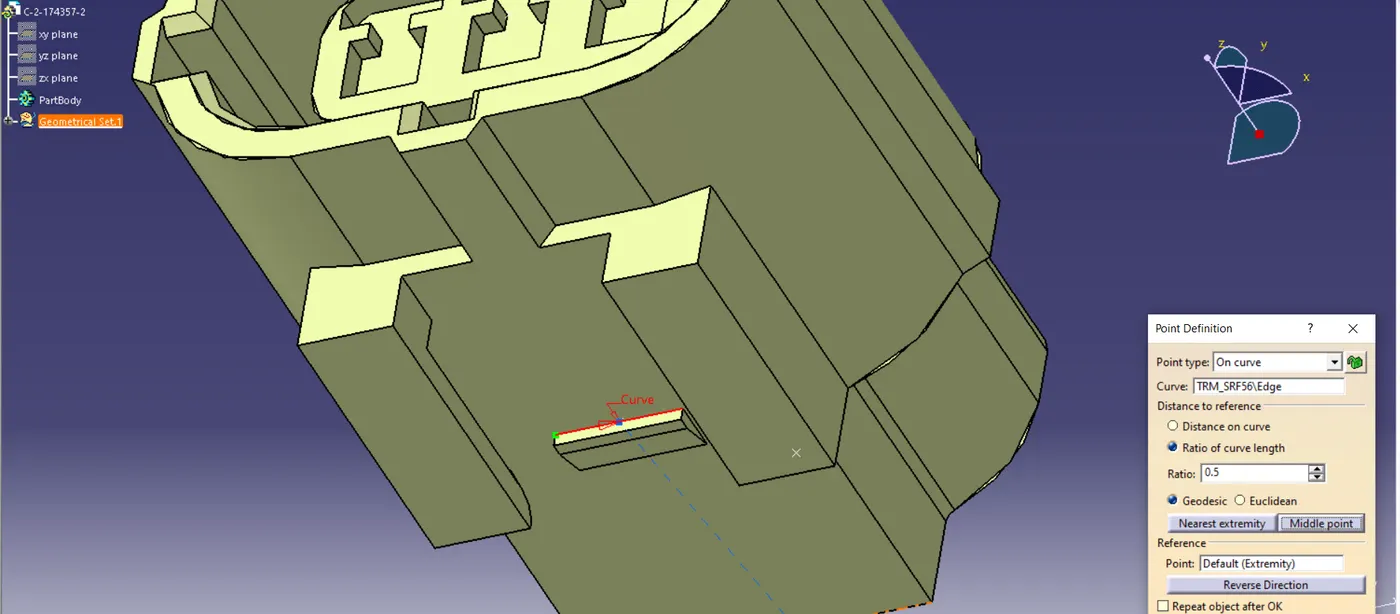
Also, in this Conector a clip is going to be attached so, we have to create an additional point for the clip mounting. So created a point using curve and middle point option on this.
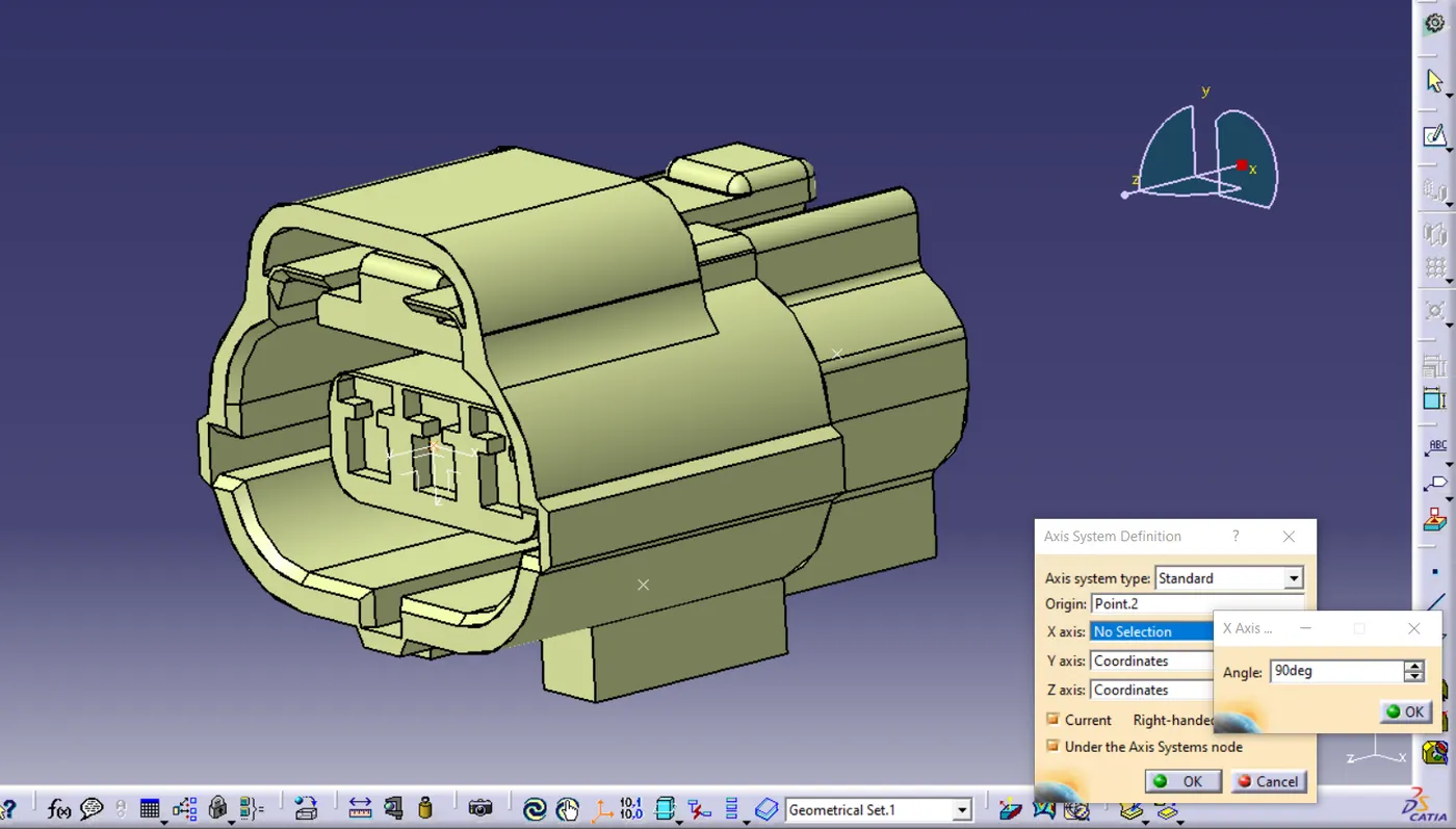
Created axis on the connector side and rotating 90deg along the x-axis.
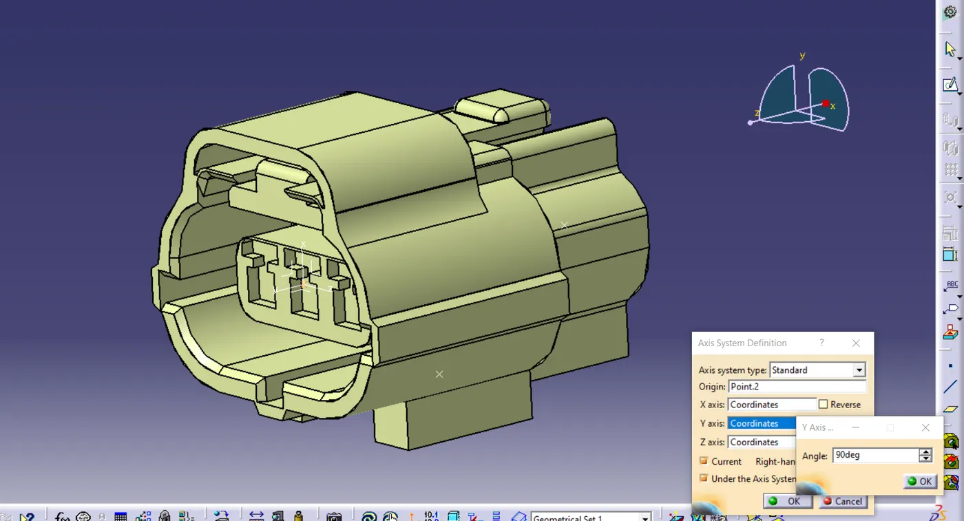
again rotating 90deg along Y-axis.
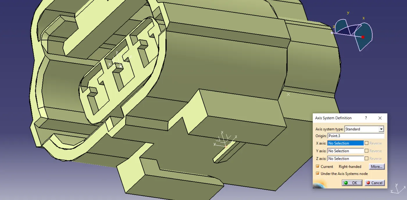
Similarly, created an axis for clip side.
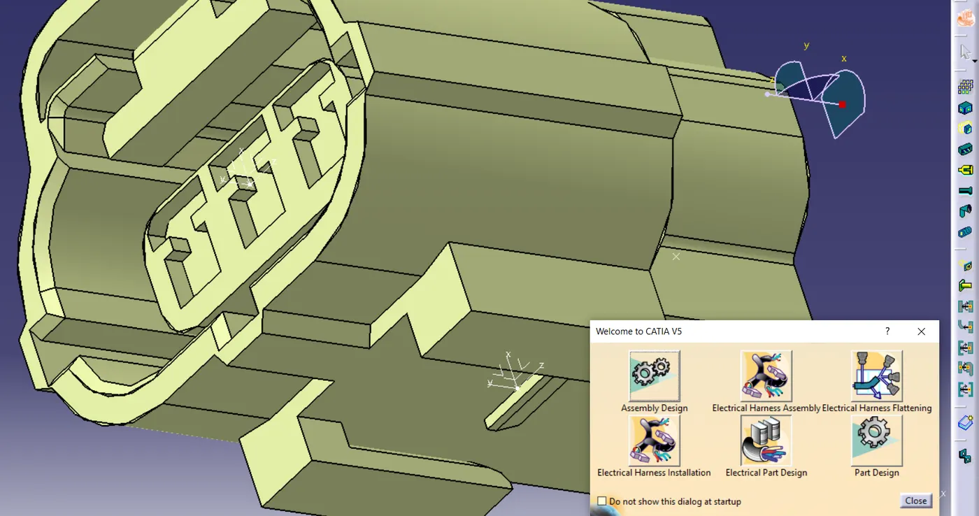
Now, Moving to Electrical Part Design
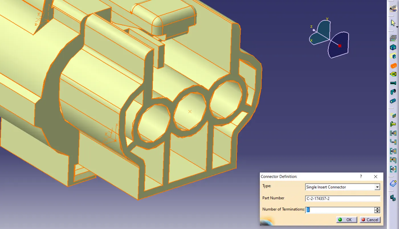
Defined the Connector Definition by setting Number of Terminations - 3
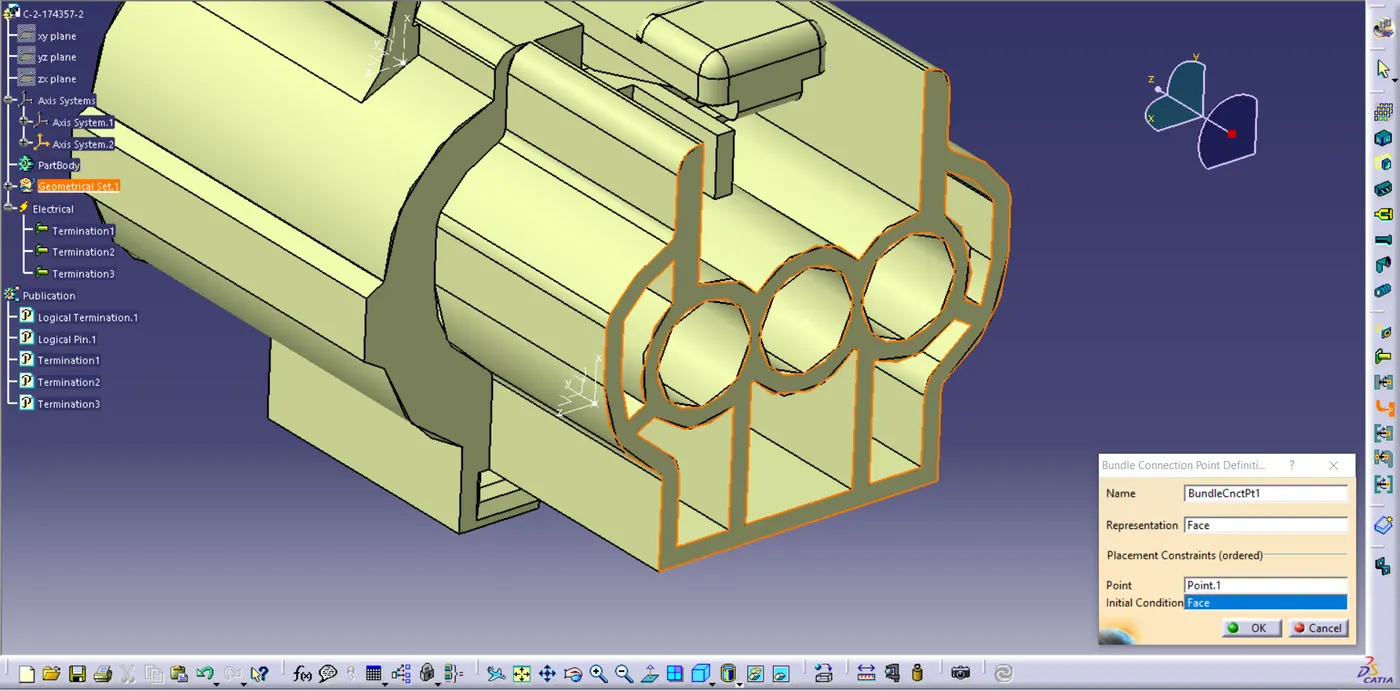
Defined the Bundle Connection Point.
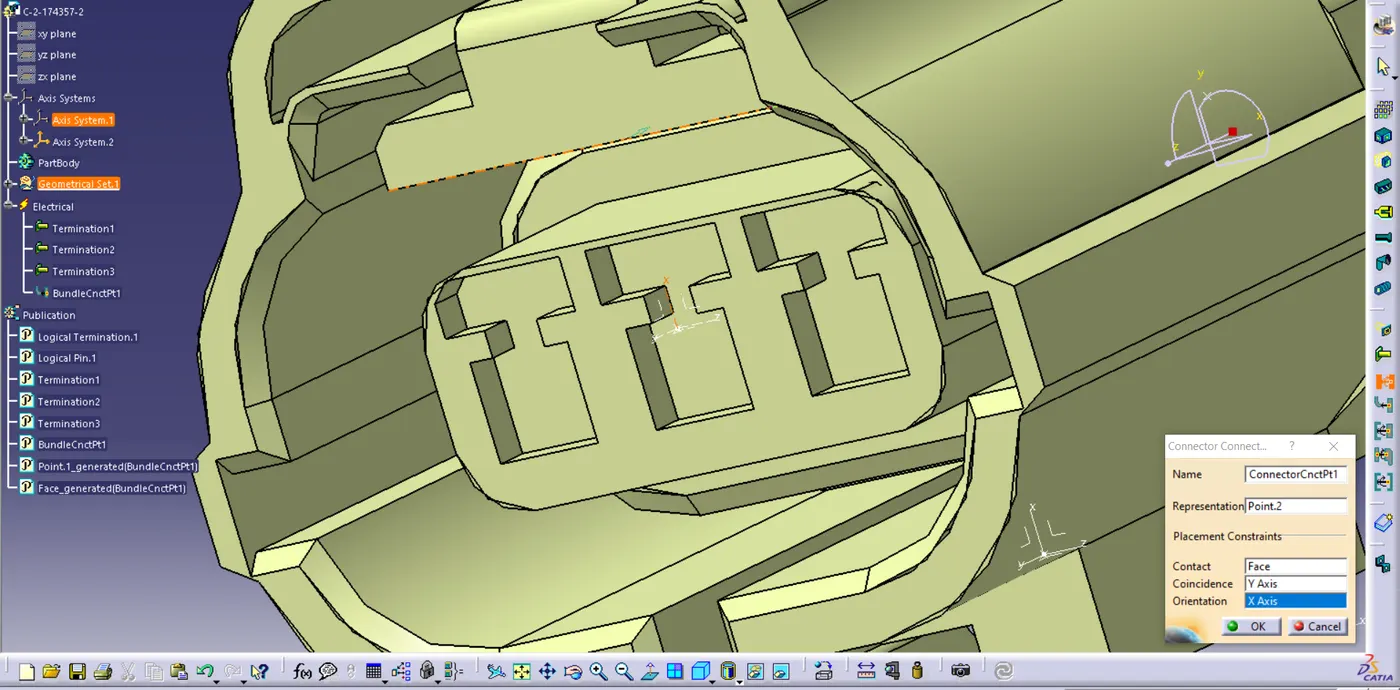
Defined the connector Connection Point
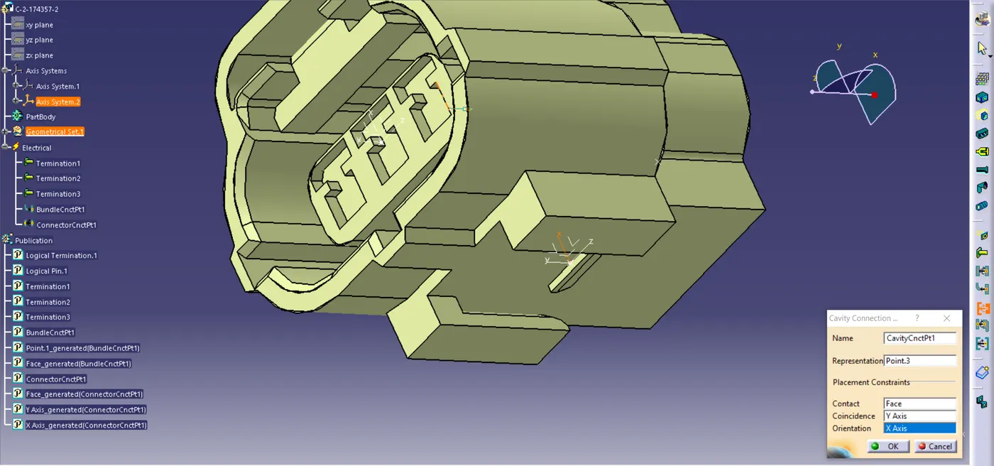
Defined the Cavity Connection Point.
3. Tyco 174357-1
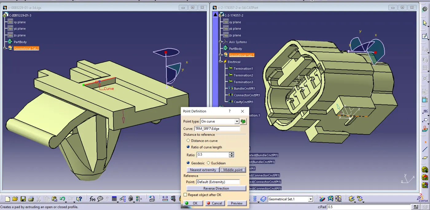
In this Figure Open the Clip and the Connector Side by side, And Defining the Point on the Clip using curve and middle point.
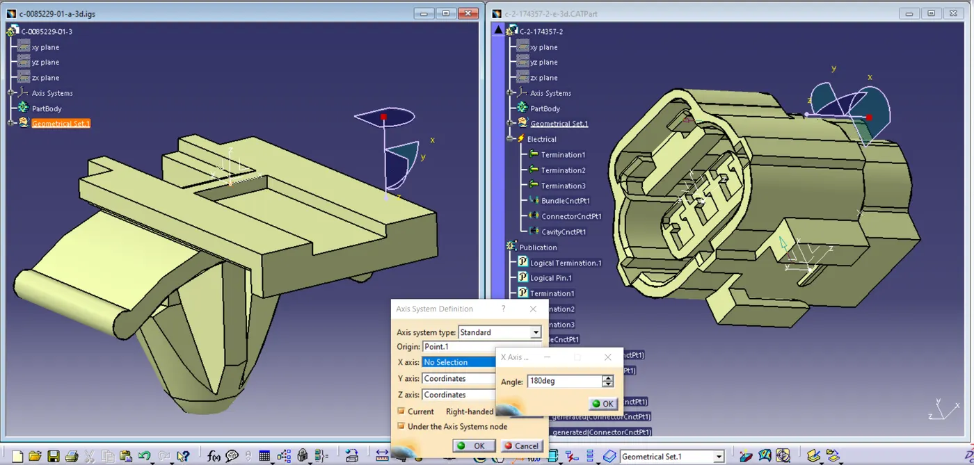
Defining the axis system by rotating 180deg along x-axis.
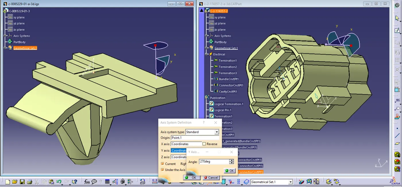
and also rotating 270deg along y-axis.
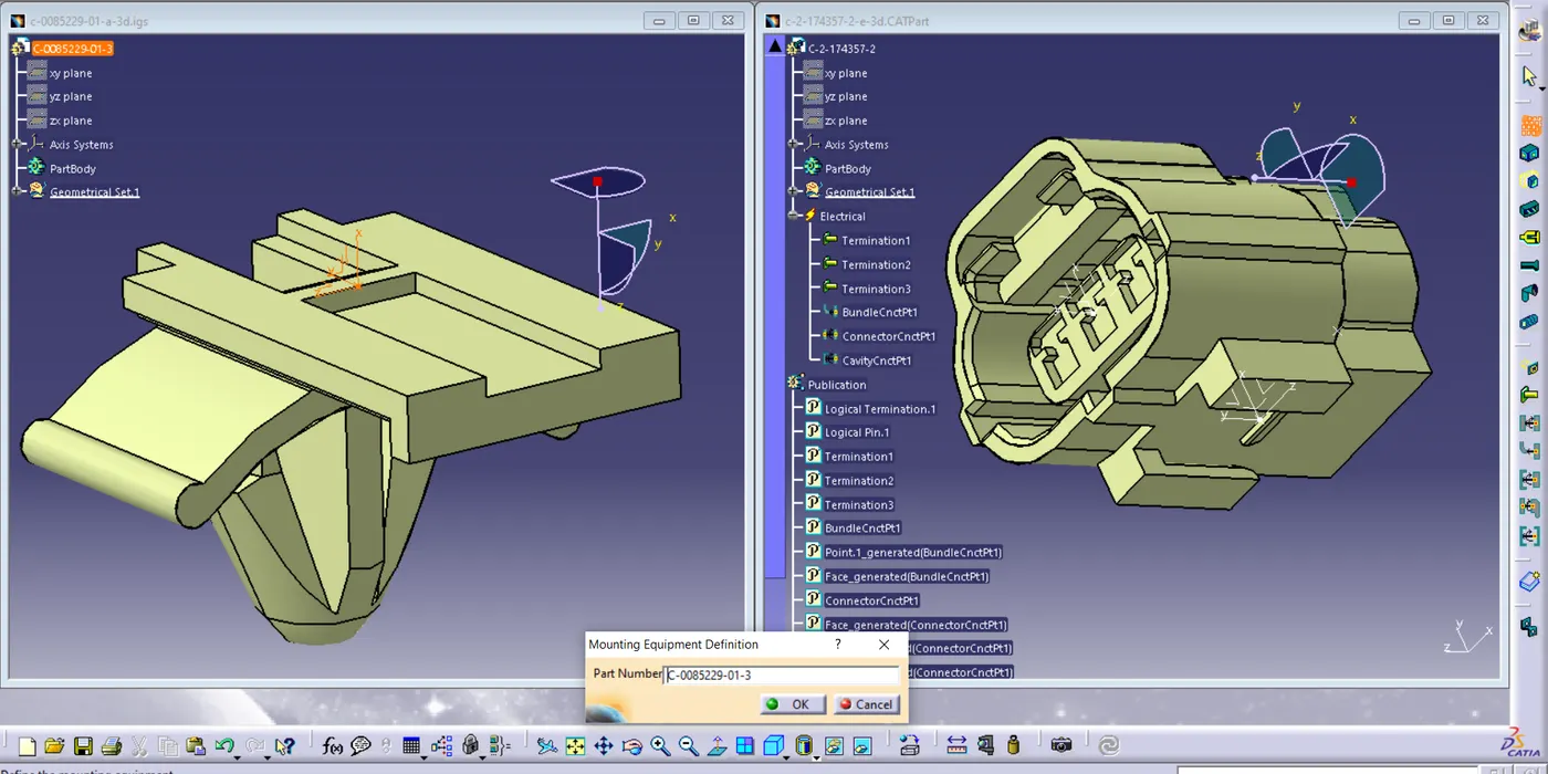
Here Defined Clip as Mounting Equipment in Electrical Part Degin.
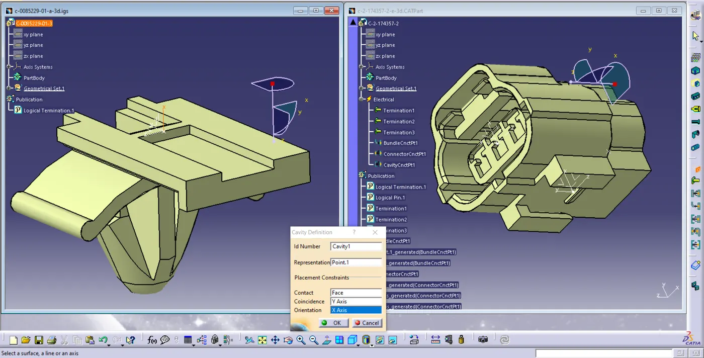
Here, Cavity Definition is done.
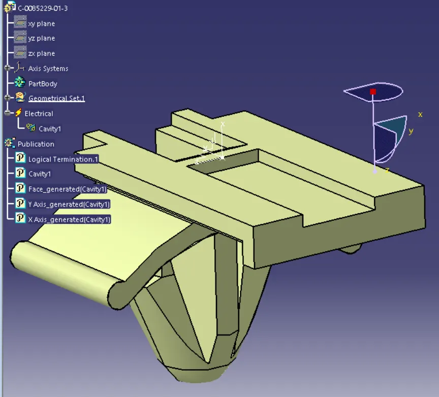
In the above figure the Tree Structure is Shown For the Clip.
Assembly of the Clip and Connector.
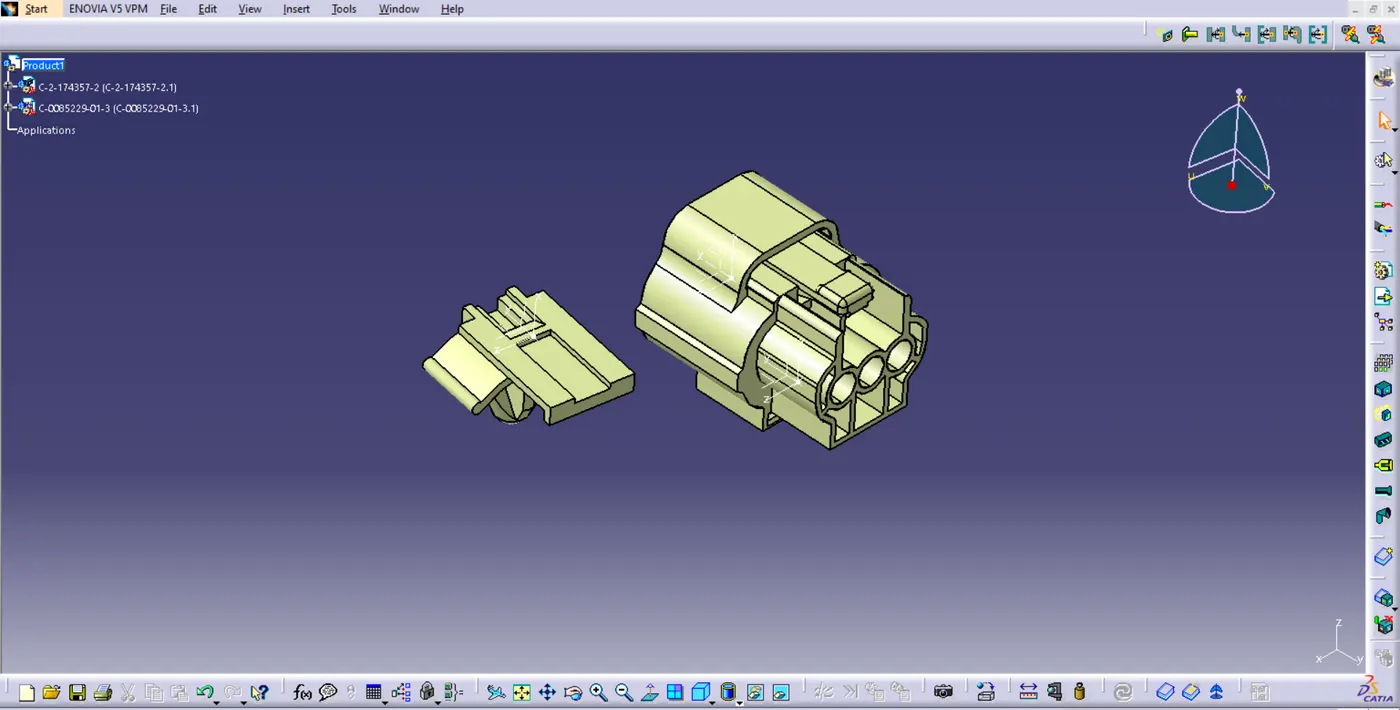
Here, Opened the Electrical Assembly Design, and opened the two parts in this.
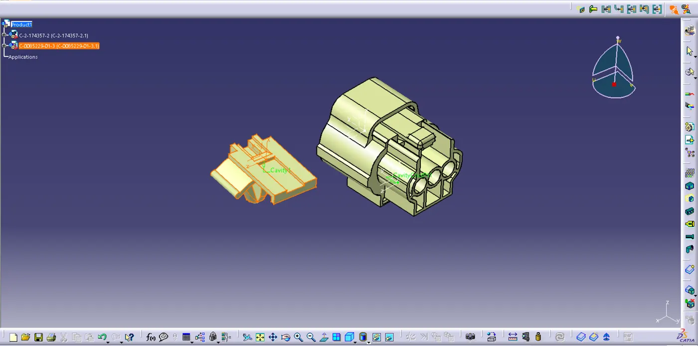
Using the addition tool first selected the clip then on hovering on the connector we can see the cavity connection point and axis are showing, After selecting the cavity connection point the two parts are assembled together, which we can see in the below image.