Wiring harness design in CATIA V5 - 3D modeling Week 2 Challenge
#Component
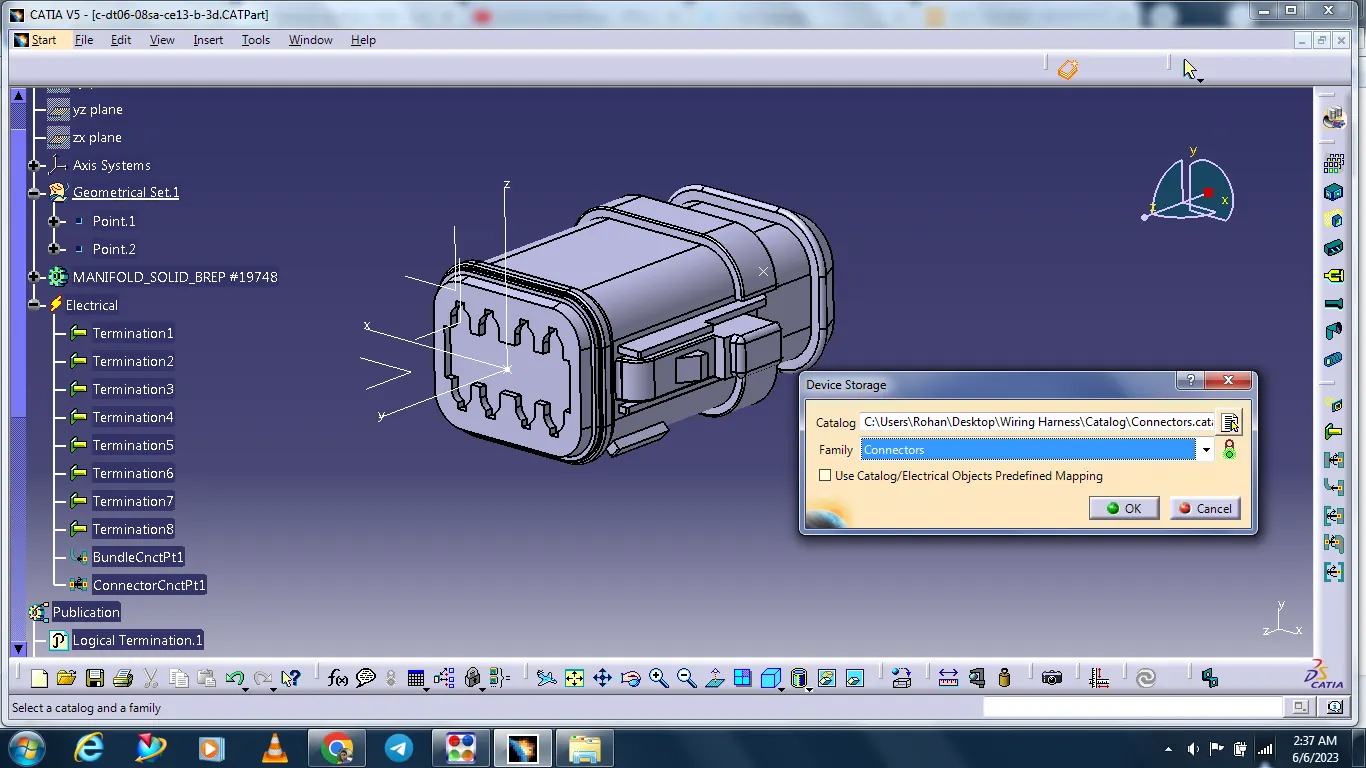
Deutsch DT06 – 08SA
This cad data is downloaded from the given link.
The data is inserted in cad.
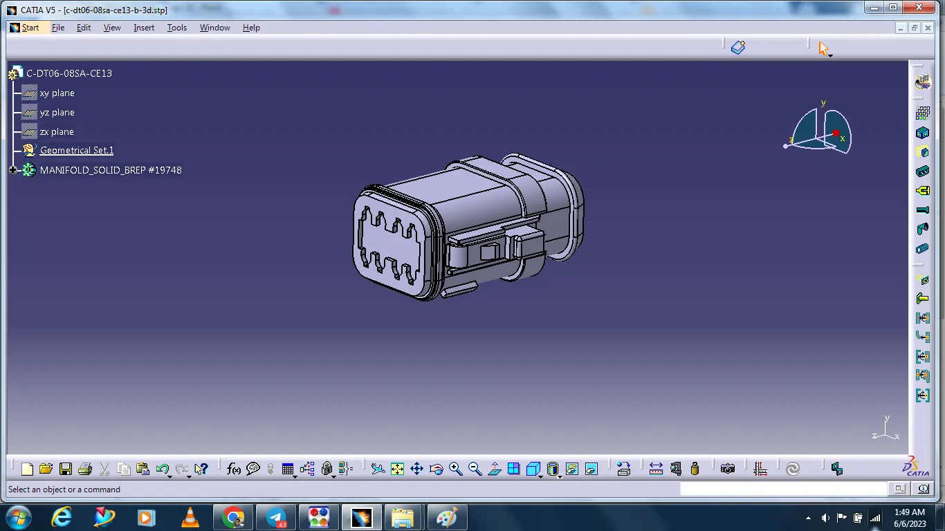
Geometry Parameters
Harness bundle entry point:
This point is defined where the harness bundle segment point will end when routed to the electrical connector.
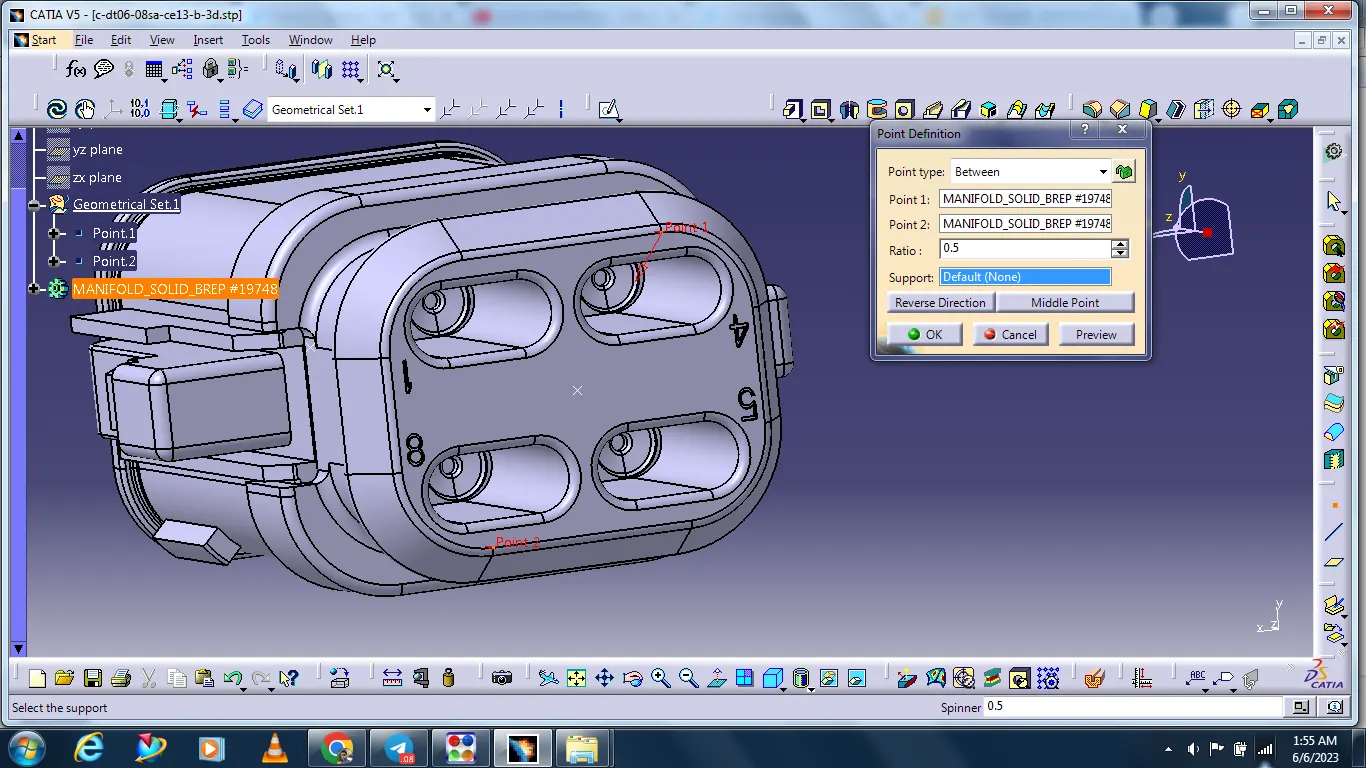
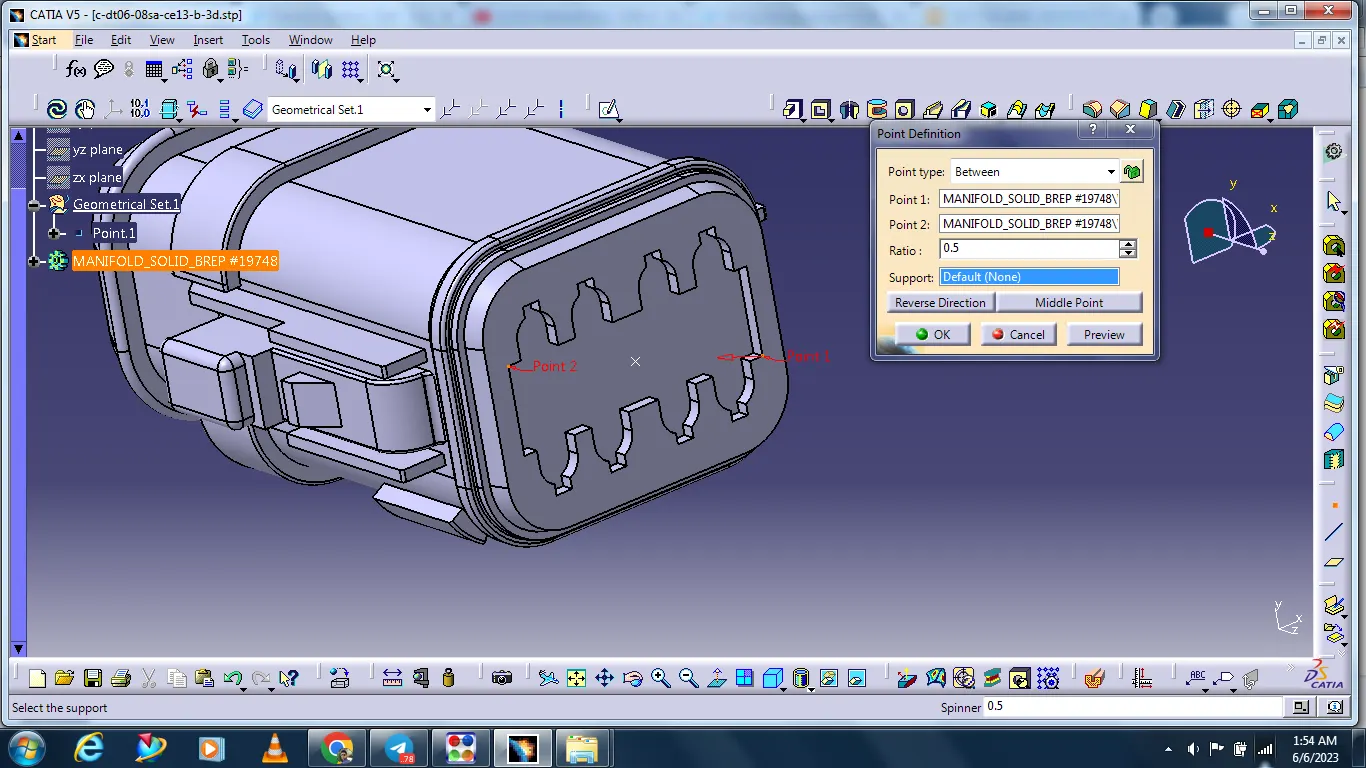
Connector connection point:
This point is used for the connection of one connector to another connector.
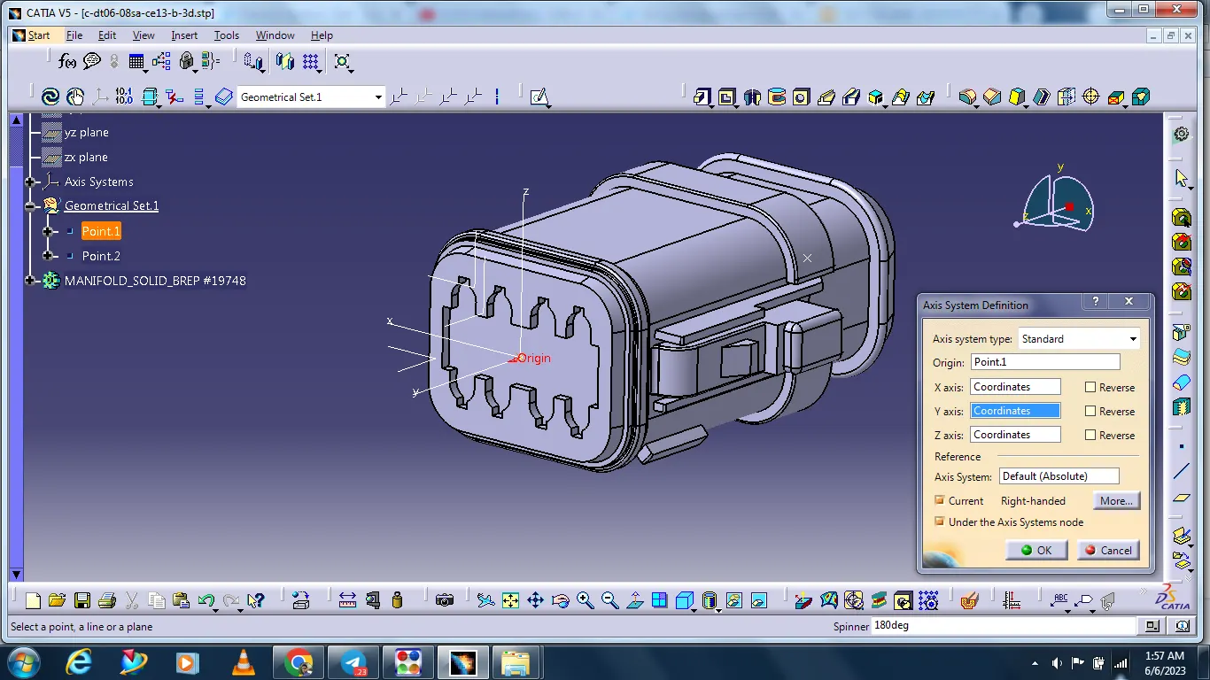
Creating the connector axis system.
Select start - Mechanical design - Part design
The connector axis system should be on the front face of the connector attached to a point on 0,0,0 co-ordinates.
This point should be in the center of the front face as this point will be used to connect the connector to another electrical component.
Connector Definition.
The component is defined as the connector using the Define Connector tab in the Electrical Part Workbench. The number of terminals is defined.
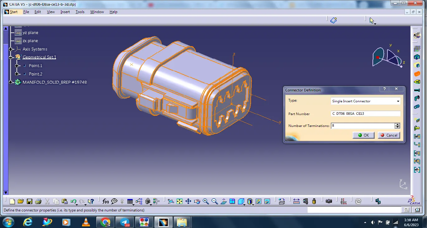
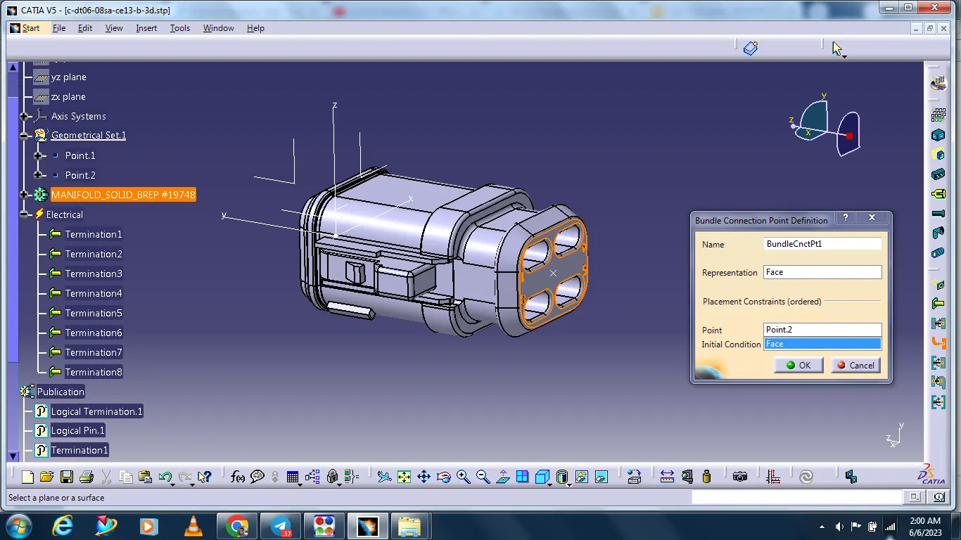
Bundle connection point definition.
the bundle connection point is defined using the Bundle Connection Point Definition tab in the Electrical Part Workbench. The parameters are defined appropriately.
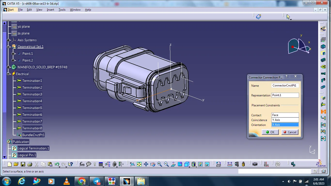
Connector connection point
Select the connector connection point icon from the workbench
Select the connector
In the connector connection box is open there is having contact option there select the connector face. And the Coincidence option side select the Y axis and on the Orientation option side select the X axis.
#Component
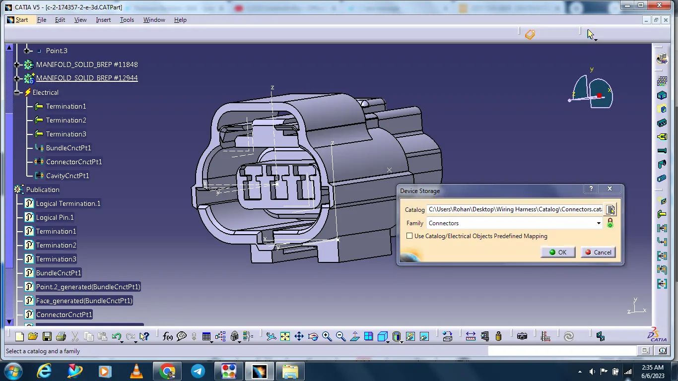
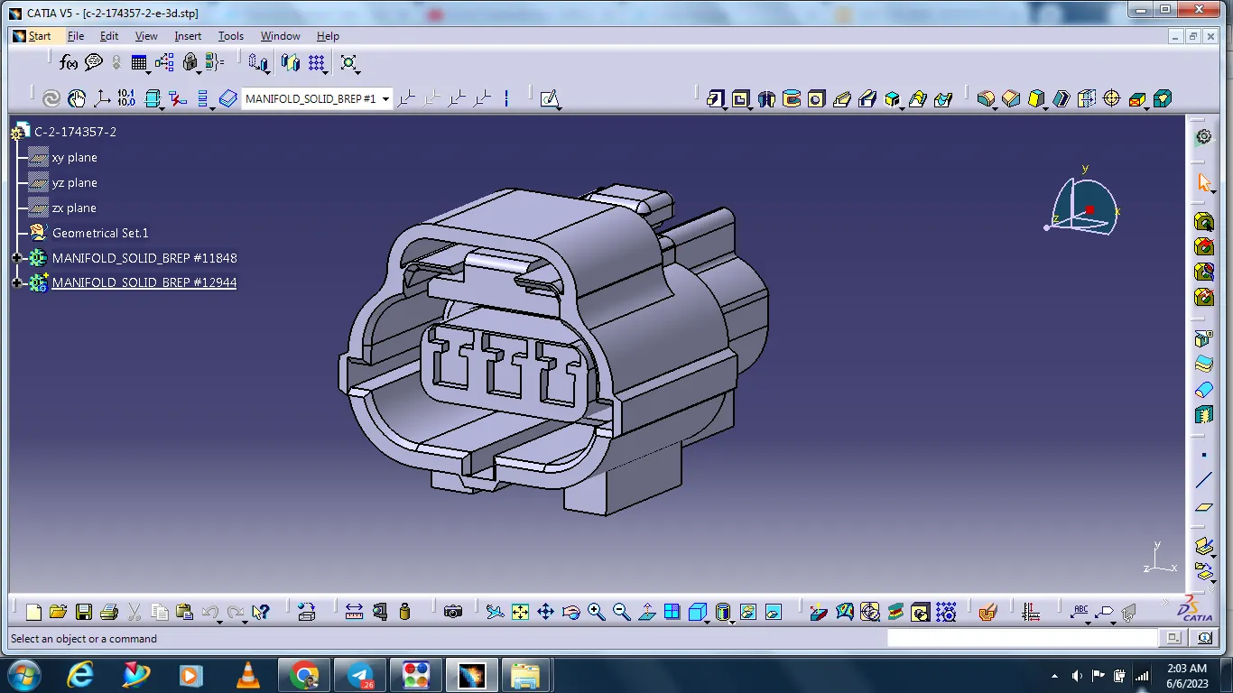
Tyco 174357-2
The data is inserted in cad
Geometry Parameters
Harness bundle entry point:
This point is defined where the harness bundle segment point will end when routed to the electrical connector.
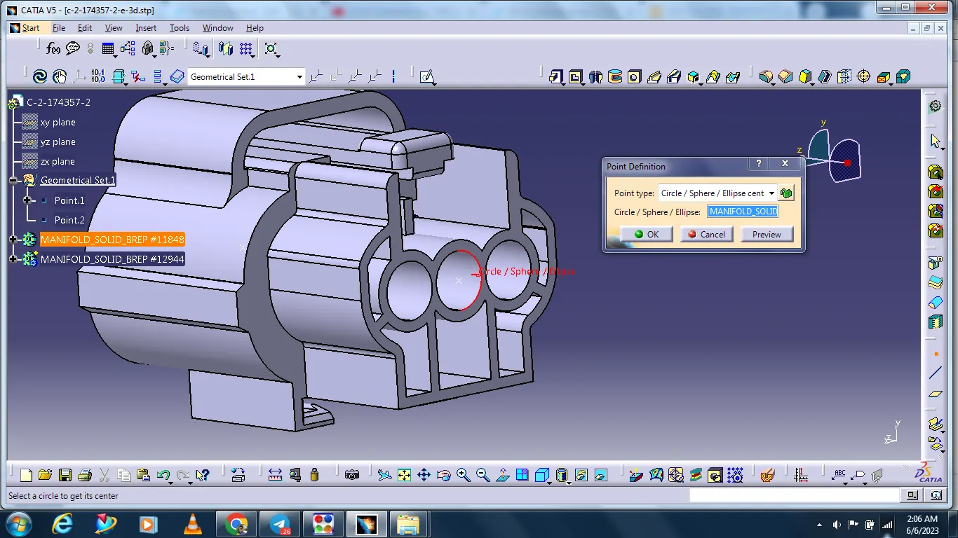
Connector connection point:
This point is used for the connection of one connector to another connector.
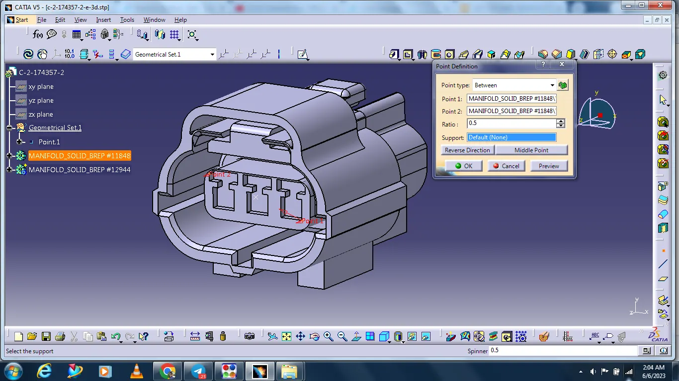
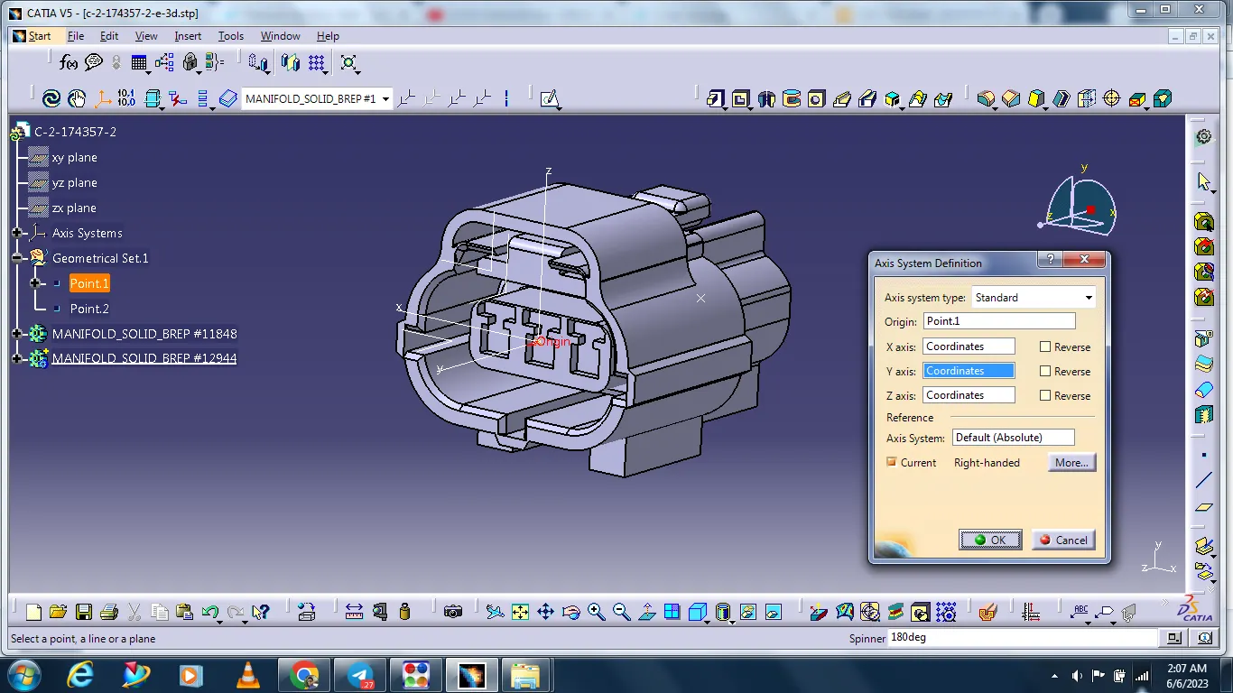
Creating the connector axis system.
Select start - Mechanical design - Part design
The connector axis system should be on the front face of the connector attached to a point on 0,0,0 co-ordinates.
This point should be in the center of the front face as this point will be used to connect the connector to another electrical component.
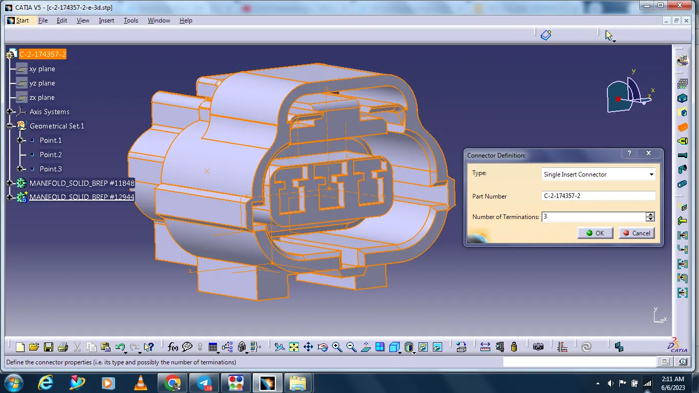
Connector Definition.
The component is defined as the connector using the Define Connector tab in the Electrical Part Workbench. The number of terminals is defined.
Bundle connection point definition.
the bundle connection point is defined using the Bundle Connection Point Definition tab in the Electrical Part Workbench. The parameters are defined appropriately.
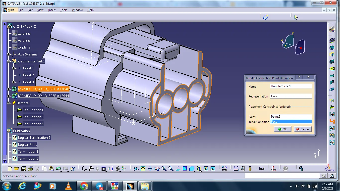
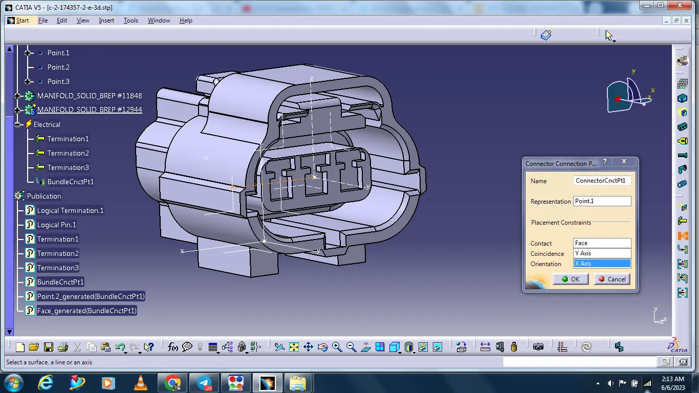
Connector connection point
Select the connector connection point icon from the workbench
Select the connector
In the connector connection box is open there is having contact option there select the connector face. And the Coincidence option side select the Y axis and on the Orientation option side select the X axis.
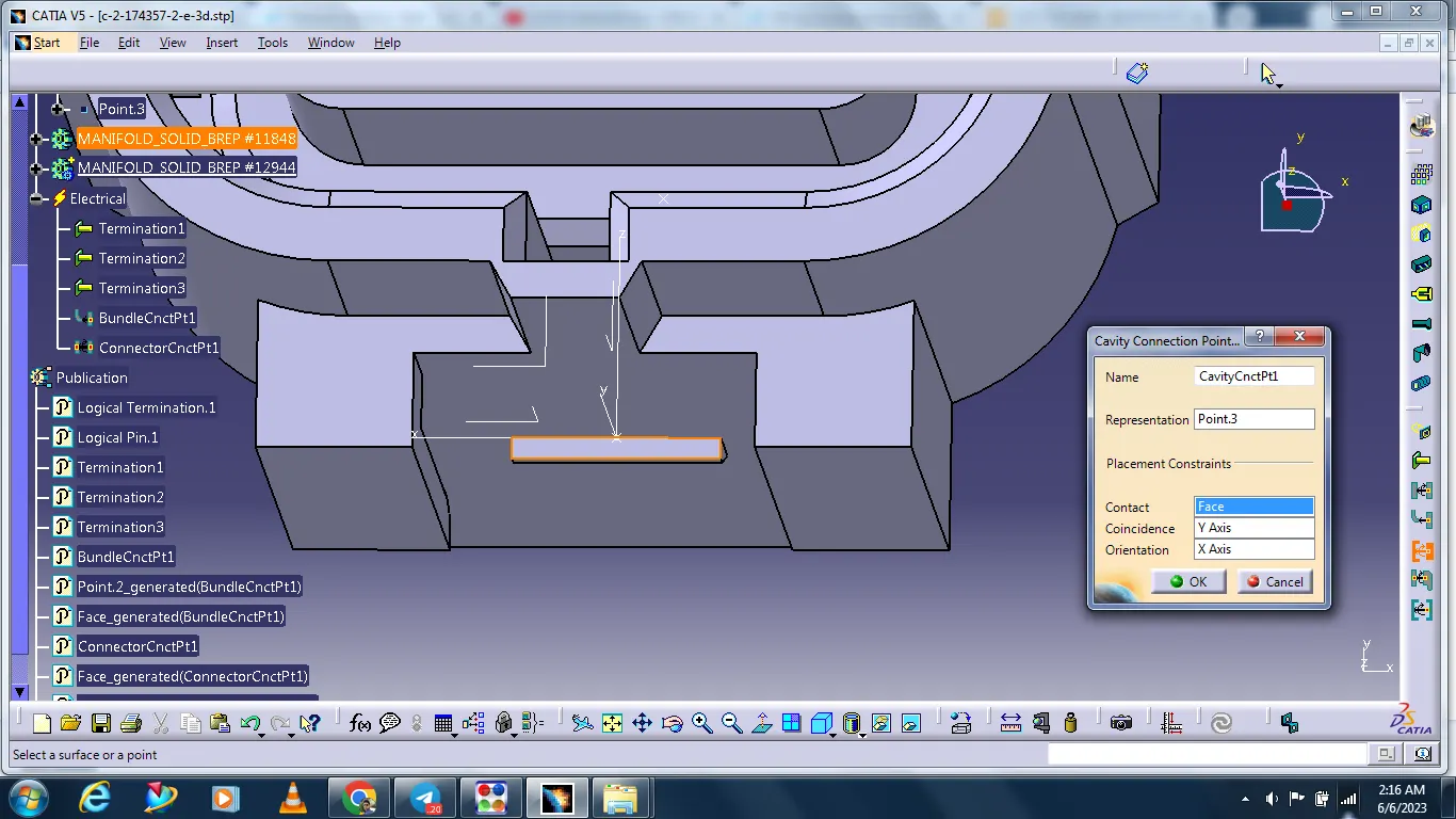
The clip mounting area side point creating.
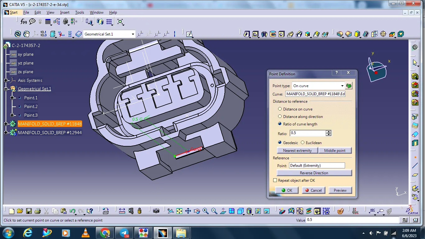
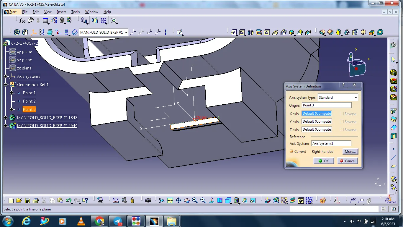
Cavity connection point
This point is used to define the connection of a connector to a connector clip.
This only applies to connectors that have the mounting feature for a connector clip.
#Component
Tyco 85229-1
The data is inserted in cad.
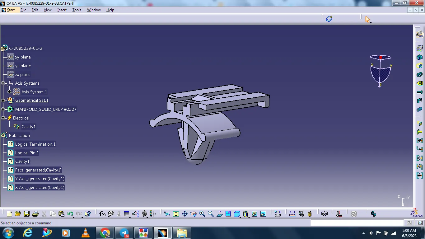
Cavity Point:
The Cavity Point is created at the cavity position of the connector.
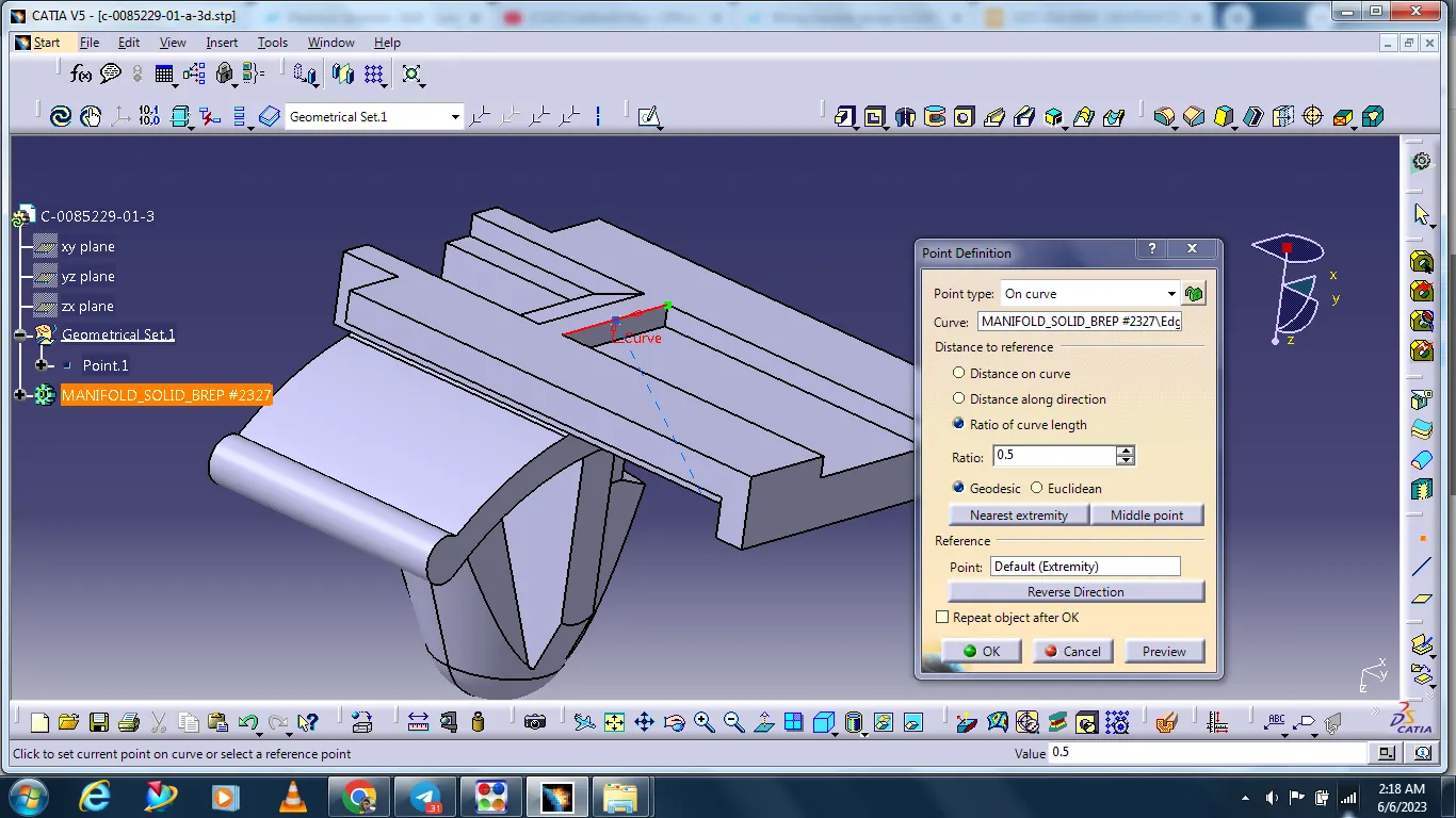
Creating the connector axis system.
Select start - Mechanical design - Part design
Create the axis system to connect the connector
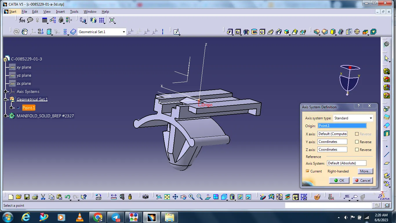
Definition of Equipment:
The component is defined as equipment using the Define Equipment tab in the Electrical Part Workbench.
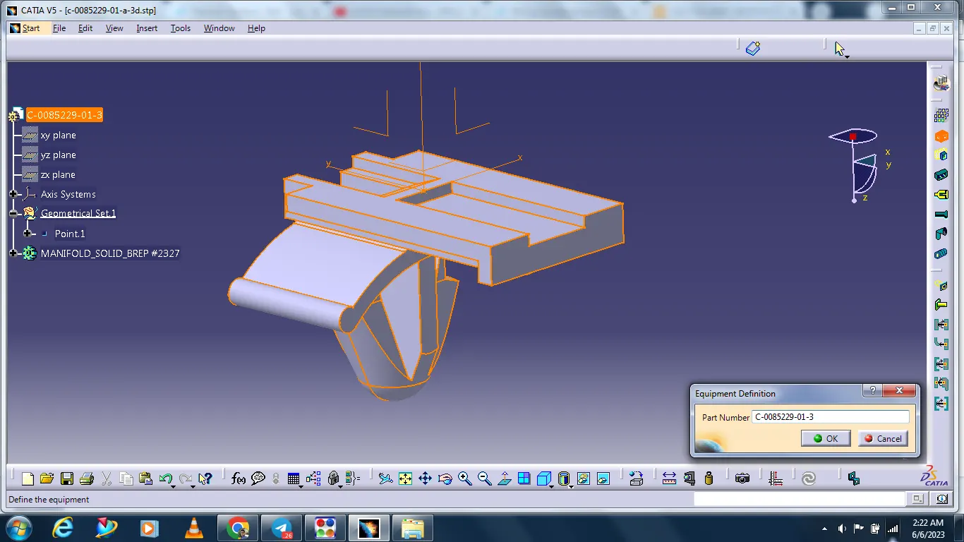
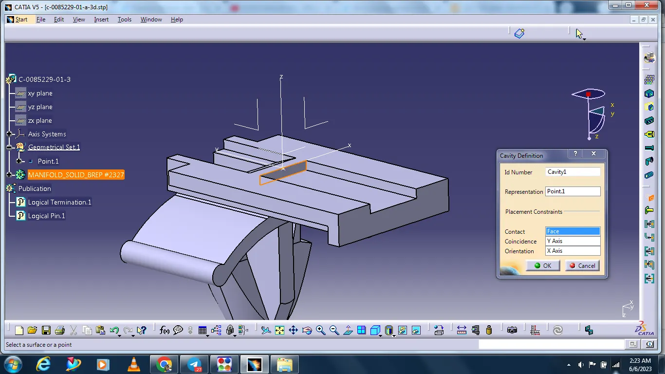
Cavity definition:
Select the cavity definition icon.
The cavity definition box is open select the clip.
Select the point and the contact option side is select the meeting face. And the Coincidence option side select the Y axis and on the Orientation option side select the X axis.
#Catalog
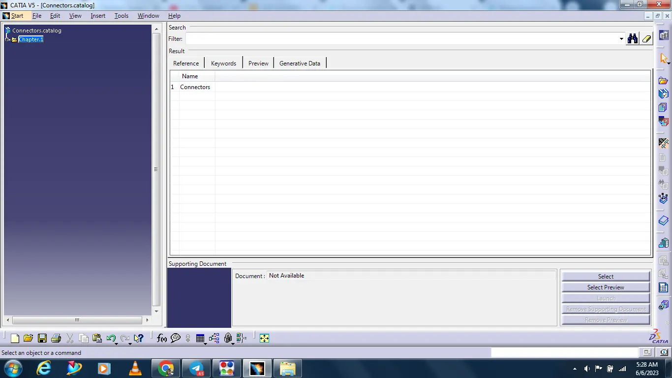
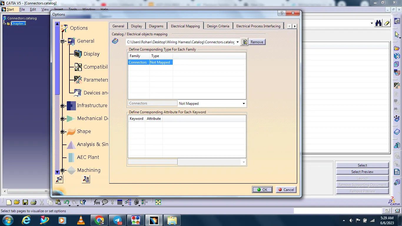
The connectors are adding in catalog.