Wiring harness design in CATIA V5 - 3D modeling Week 2 Challenge
WIRING HARNESS DESIGN IN CATIA V5 - 3D MODELING WEEK 2 CHALLENGE
AIM:
To download following connectors & Connector clip cad data from given link & define it as Electrical Connector using Electrical Part design Workbench and Define all the necessary properties To Connectors & Clip.
WIRING HARNESS DESIGNING PROCESS:
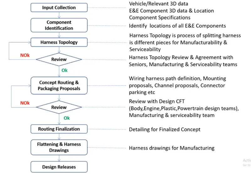
ELECTRICAL DISTRIBUTION SYSTEM:
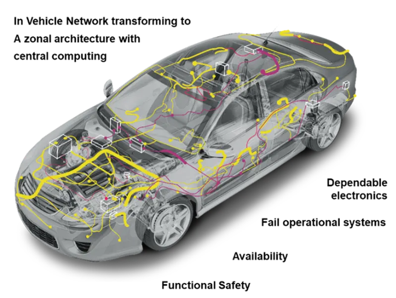
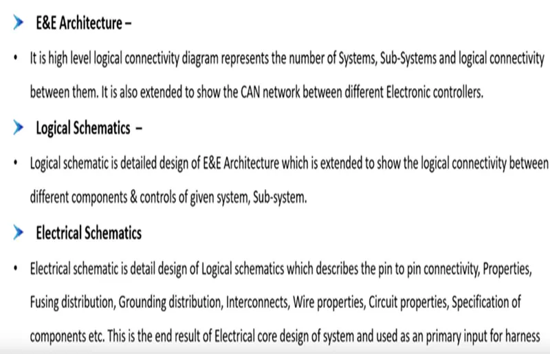
Electrical distribution system deals with physical and logical architecture, schematic development, power distribution, wiring harness design, wiring harness component design of given electrical system.
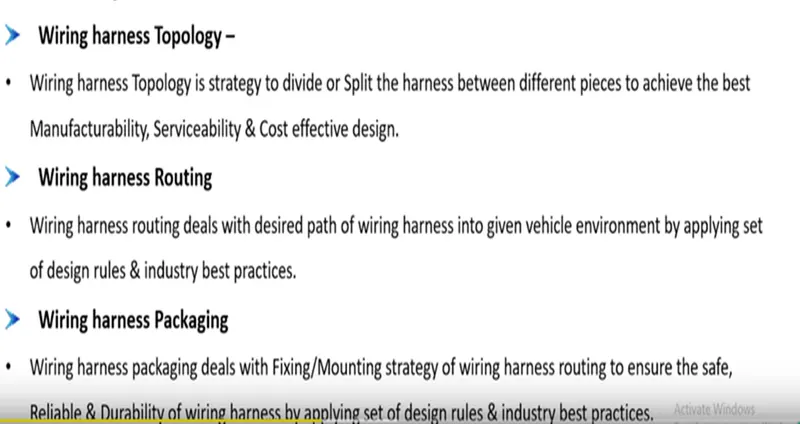
CONNECTORS:
Connectors are the electro-mechanical devices used to form a continuous electronic signal to connect wire harnesses to a power source or circuit. On a basic level, connectors consist of male-ended plugs and female-ended jacks that can be joined together to relay an electronic signal.
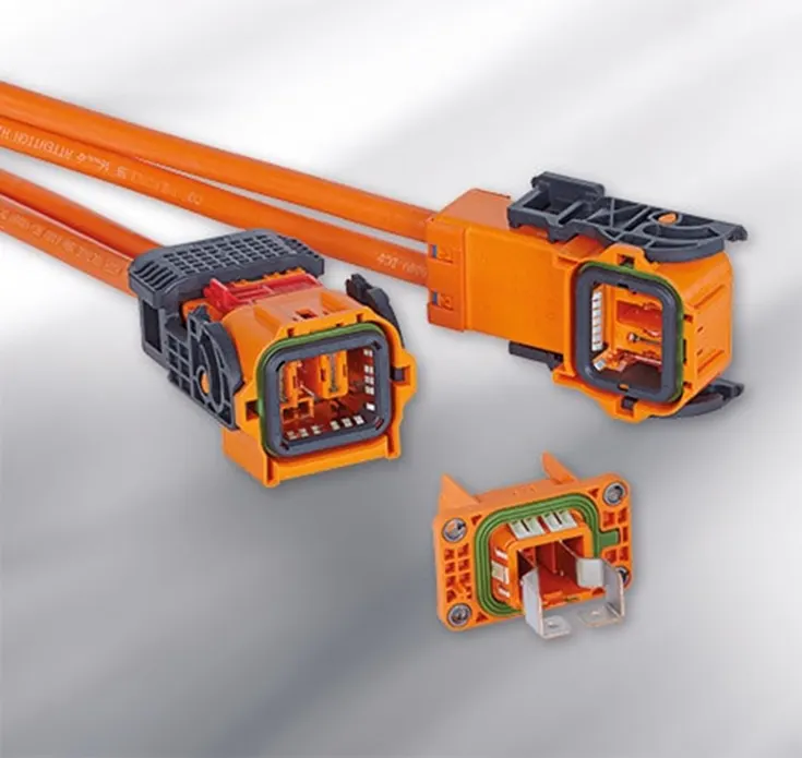
GIVEN CONECTOR DATA:
- Deutsch DT06 – 08SA ( https://www.te.com/usa-en/product-DT06-08SA.html)
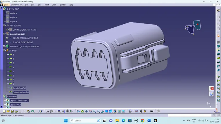
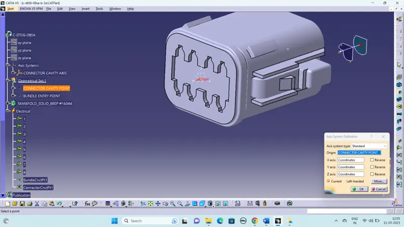
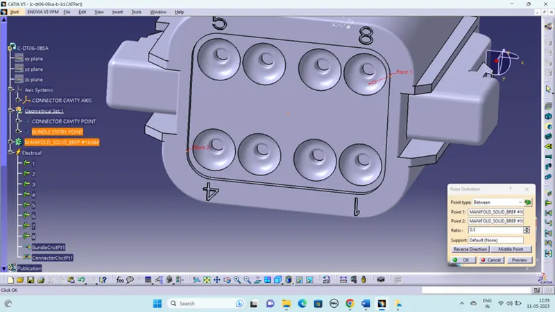
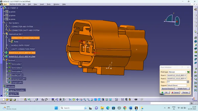
- Create midpoint on the contact face which will be normal to wire bunddle insertion.
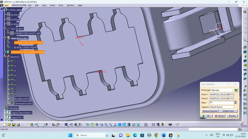
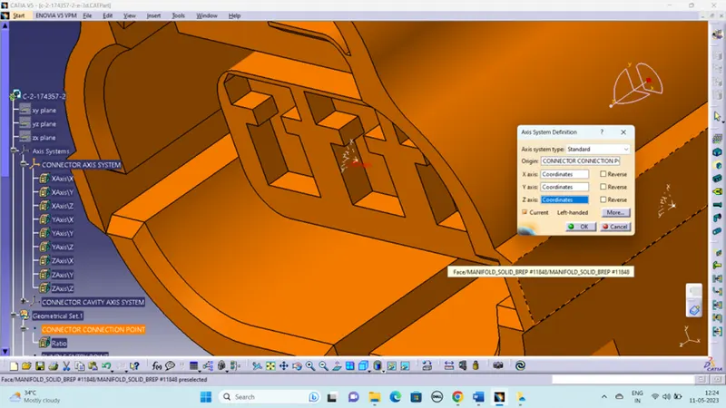
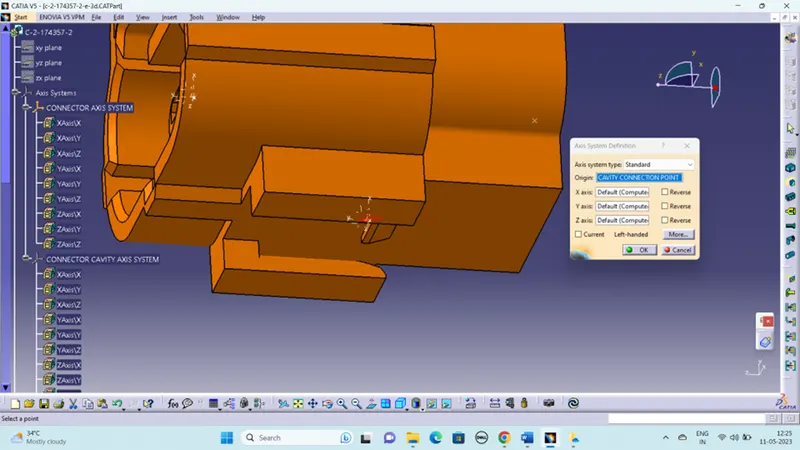
- Create Axis System with respect to the point which we have created and defining the axis direction as shown below,
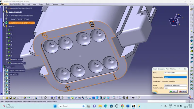
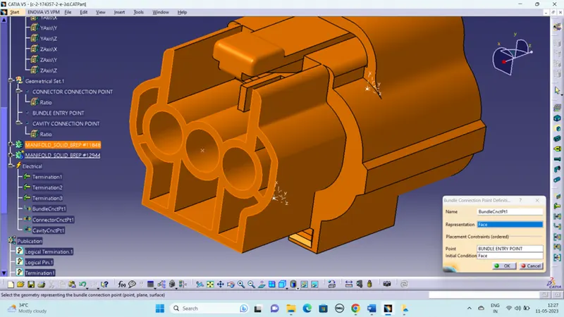
BUNDLE CONNECTION POINT:
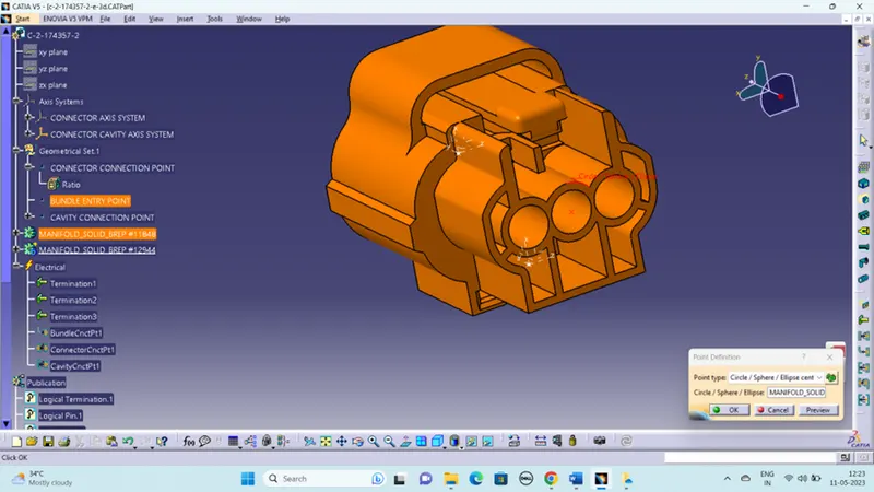
This point is located at center of the bundle segment side or wire entry side. This is the point where bundle segment or wire point end when get routed to a connector. This point is known as Bundle Connection Point.
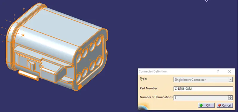
Switch to 'Electric Part Design'
Define the part as connector in CATIA, give no. of termination as 8 because we have 8 entry points for wire.
Define Bundle connection point:
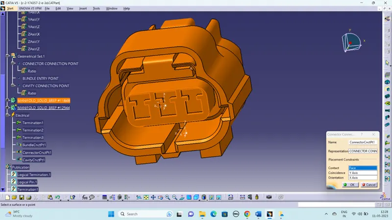
Define connector connection point:
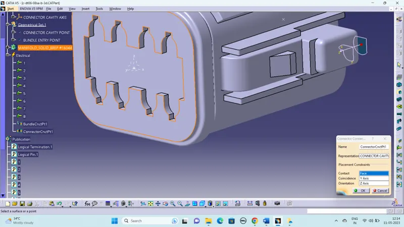
TREE STRUCTURE:
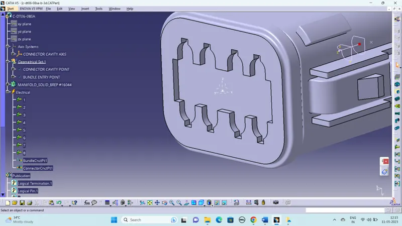
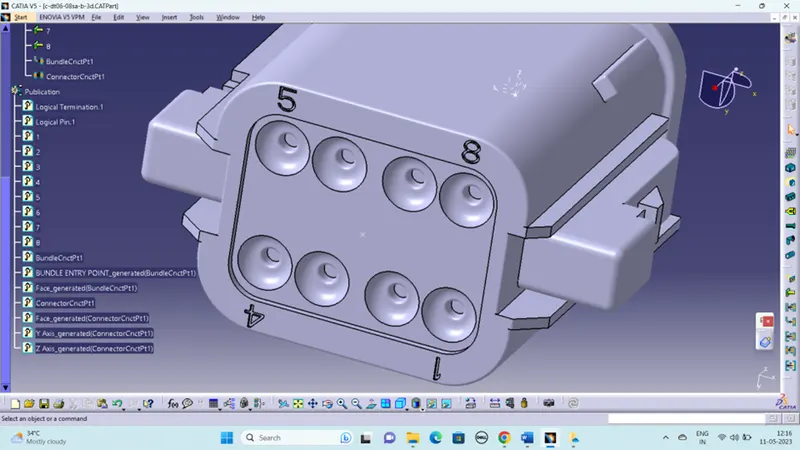
GIVEN CONECTOR DATA:
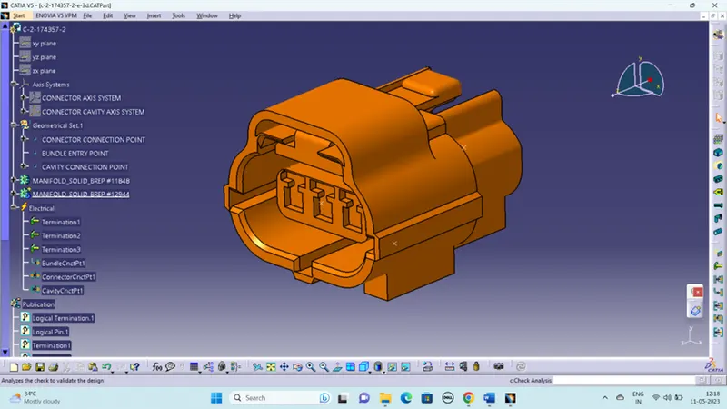
- Create midpoint
- Create Connector connection point
- Create bundle connection point
- Create Connector connection axis system
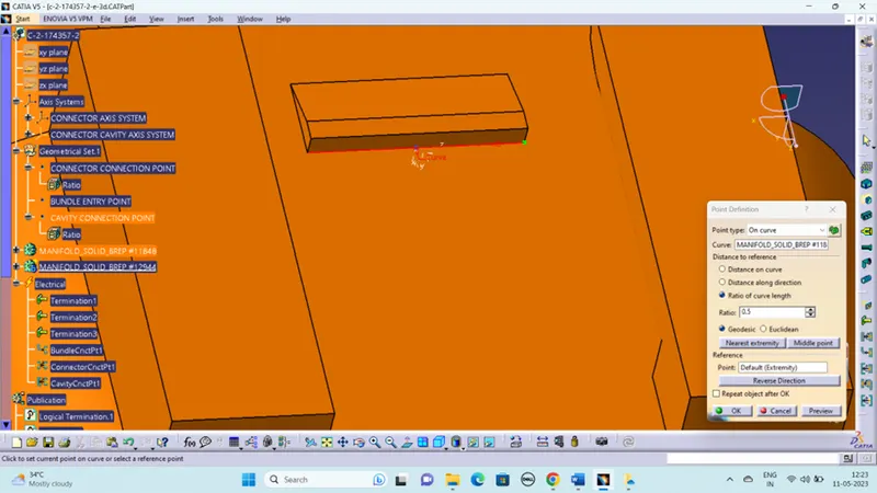
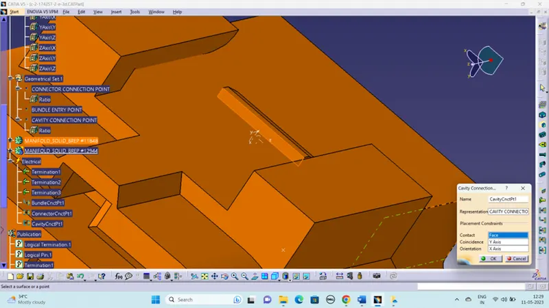
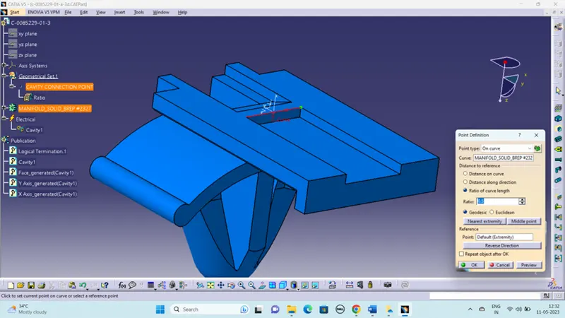
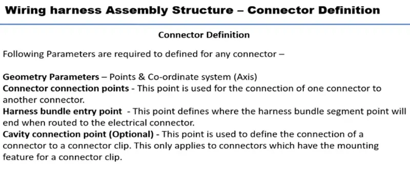
- Create cavity connection point
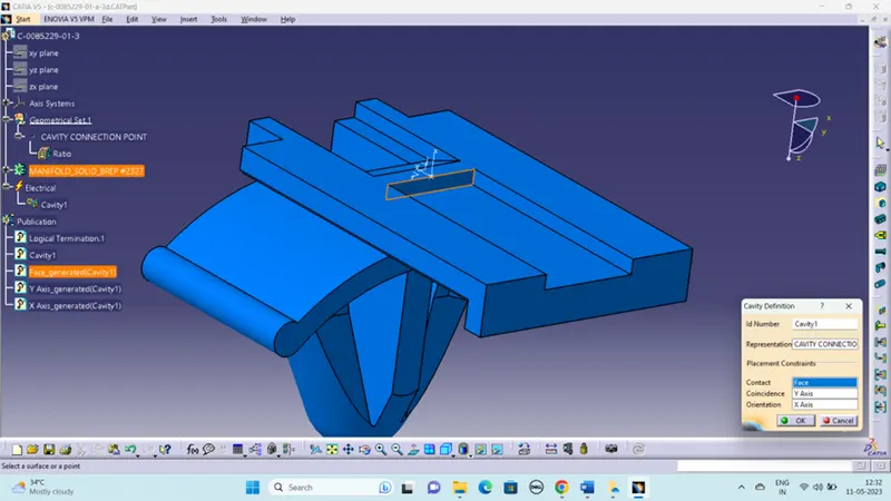
- Create cavity connection axis system
- Switch to Electric part design and define part as connector
- Define Connector connection point and cavity connection point
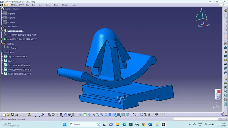
GIVEN CLIP DATA:
- Tyco 85229-1 – (https://www.te.com/usa-en/product-85229-1.html?q=85229&source=header)
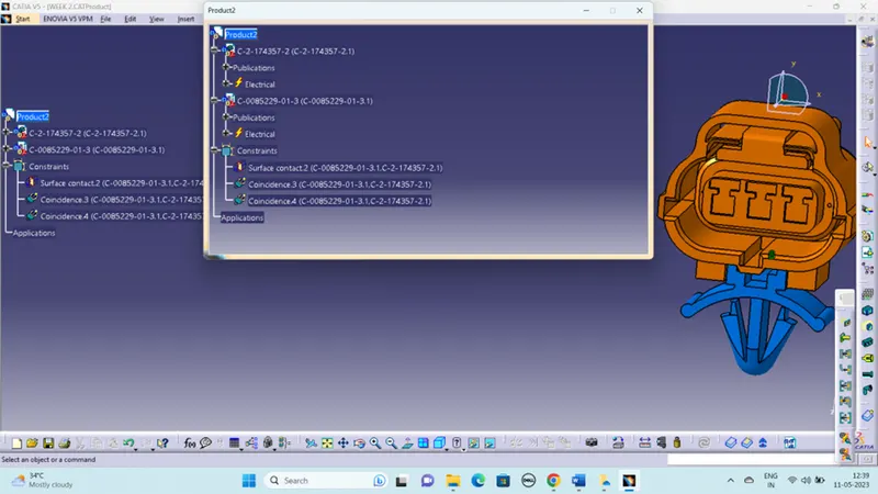
Electrical Assembly Design
- Import Connector and cavity / mounting clip.
- Select Defining Electric connection
- select cavity and then connector.
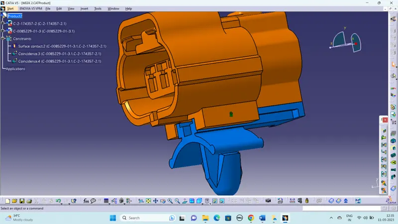
TREE STRUCTURE: