Wiring harness design in CATIA V5 - 3D modeling Week 2 Challenge
Aim:-
Q1. Download the following connectors & Connector clip cad data from the given link & define it as Electrical Connector using the Electrical Part Design Workbench. Define all the necessary properties of Connectors & clips.
- Deutsch DT06 – 08SA ( https://www.te.com/usa-en/product-DT06-08SA.html)
- Tyco 174357-2 (https://www.te.com/usa-en/product-2-174357-2.html?source=header-match)
- Tyco 85229-1 – (https://www.te.com/usa-en/product-85229-1.html?q=85229&source=header)
Prepare a proper report with the necessary images in the answer box provided
Solution:-
Steps to define 3D Connectors as Electrical Connectors using the Electrical Part Design Workbench -
- Create/Download connector 3D
- Mechanical Part Design
- Defining geometrical parameters by point and axis system (point for bundle/wire entry side, point and axis system for mating side).
iii. Electrical Part Design
- Define part as a connector
- Define bundle connection point (bundle/wire entry side)
- Define connector connection point (mating side)
- Define cavity connection point (optional, if connector needs mounting clip)
- Deutsch DT06-08SA
- Mechanical Part Design Workbench
- Defining geometrical properties (points and axis system)
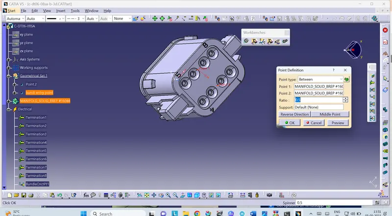
Bundle entry side center point -
Selecting two random points diagonally to get a center point, under point type between.
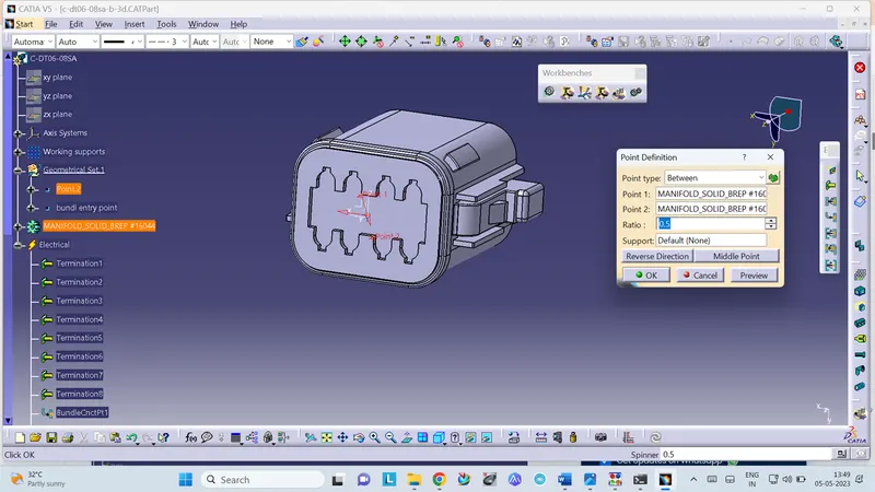
Mating side center point -
Selecting two random points diagonally to get a center point, under point type between.
Mating side axis system -
Creating an axis system concerning the center point as the origin of the axis. The Y axis is directed at the mating direction, the X axis is directed towards the locking side and the Z axis is directed upwards.
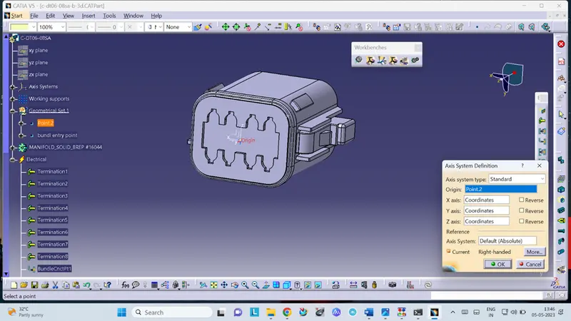
- Electrical Part Design Workbench
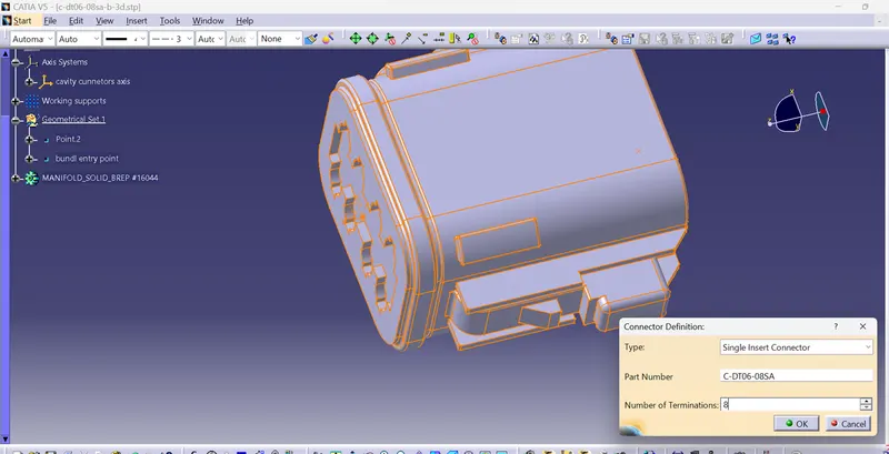
- Define part as a connector
Defining part as an electrical connector under Electrical Part Design Workbench. Selecting the number terminations 8.
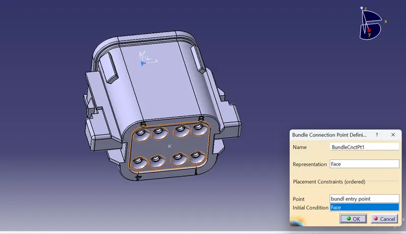
- Define bundle connection point (bundle/wire entry side)
Defining bundle connection point at the bundle entry side where, representation is the face, point as the center point, and initial condition also as the face.
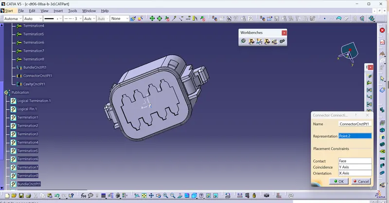
- Define connector connection point (mating side)
Defining connector connection point at the mating side of the connector where representation is the center point, contact is the face, coincidence is the Y axis, and, orientation is the X axis.
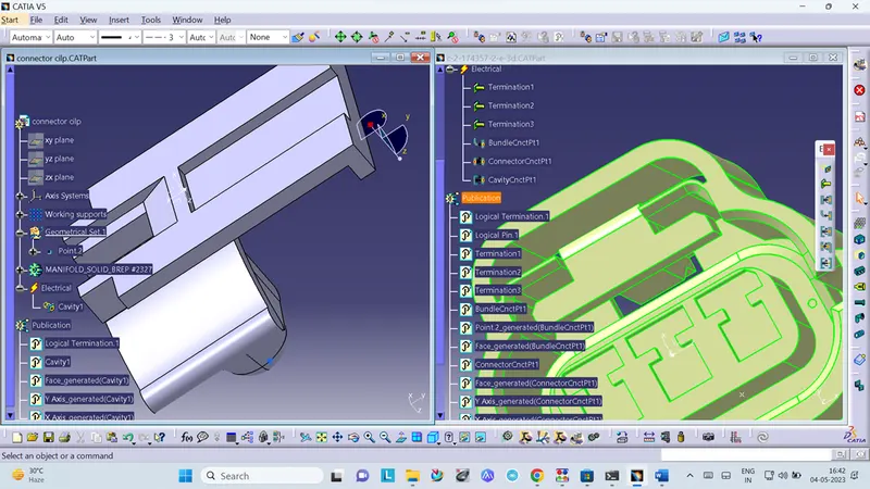
- Tyco 174357-2
- Mechanical Part Design Workbench
- Defining geometrical properties (points and axis system)
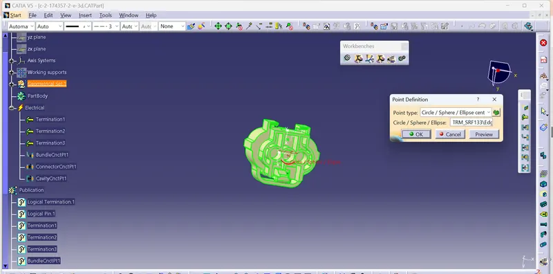
Bundle entry side center point -
Selecting two random points diagonally to get a center point, under point type circle/sphere/ellipse center.
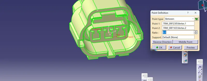
Mating side center point -
Selecting two random points diagonally to get a center point, under point type between.
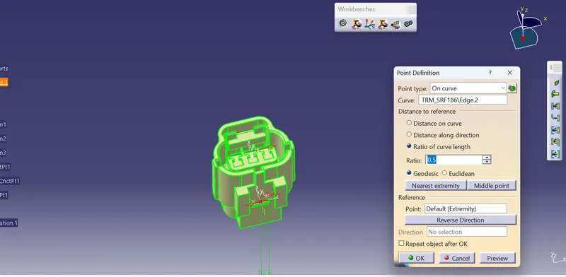
Mating side axis system -
Creating an axis system concerning the center point as the origin of the axis. The Y axis is directed at the mating direction, the X axis is directed upwards and the Z axis is directed to the side.
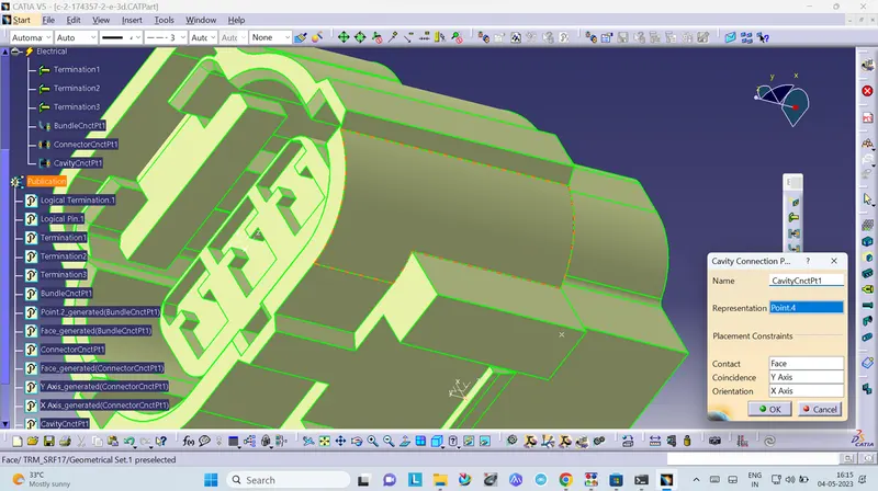
Axis system for cavity connection -
Creating an axis system concerning the center point as the origin of the axis. The Y axis is directed at the connection direction, the X axis is directed upwards and the Z axis is directed to the side.
- Electrical Part Design Workbench
- Define part as a connector
Defining part as an electrical connector under Electrical Part Design Workbench. Selecting the number terminations 3
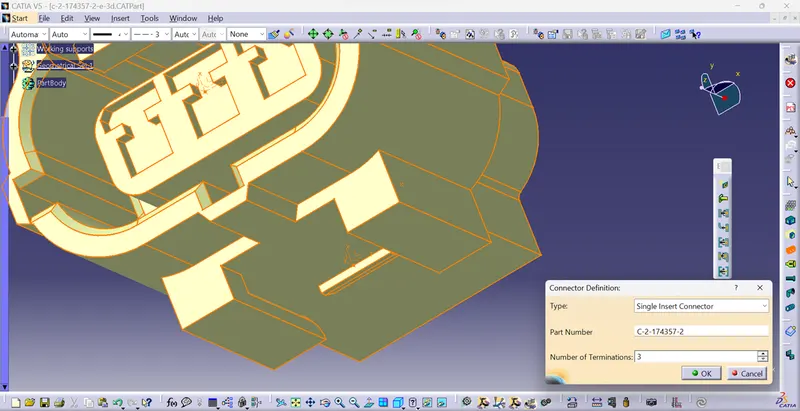
- Define bundle connection point (bundle/wire entry side)
Defining bundle connection point at the bundle entry side where, representation is the face, point as the center point, and initial condition also as the face.
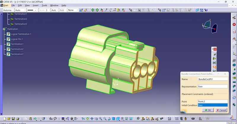
- Define connector connection point (mating side)
Defining connector connection point at the mating side of the connector where representation is the center point, contact is the face, coincidence is the Y axis, and, orientation is the X axis.
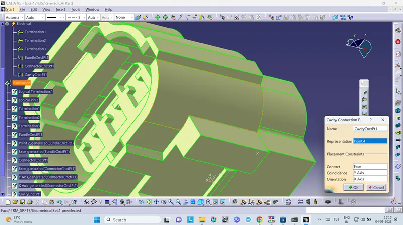
- Define cavity connection point (optional, if connector needs mounting clip)
A cavity connection is defined as the connecting part for a connector clip where representation is the center point of the cavity connection, contact is the connection face, coincidence is the Y axis and, orientation is the X axis.
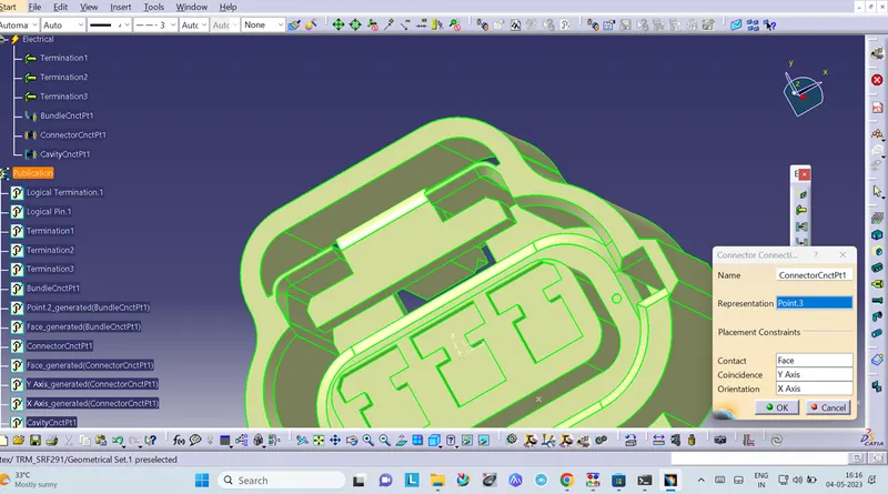
- Tyco 85229-1
- Mechanical Part Design Workbench
- Defining geometrical properties (points and axis system)
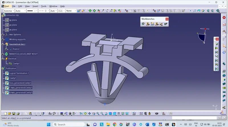
Mounting clip center point -
Selecting the edge of the connecting part to get a center point, under point type curve.
Mounting clip axis system -
Creating an axis system for the cavity, the origin is the center point, the Y axis is directed towards the insertion, the X axis is directed upwards and, the Z axis is directed to the side. The axis direction should follow the connector's cavity connection axis direction for proper mounting.
- Electrical Part Design Workbench
- Define part as a Mounting Equipment
The clip is defined as electrical mounting equipment.
Defining cavity -
A connector clip is defined as the cavity where representation is the center point, contact is the face of the connecting part, coincidence is the Y axis and, orientation is the X axis.
iii. Electrical Assembly Design Workbench
- Connect Electrical Devices
The connector and connector clip are connected under the electrical assembly design workbench using connected electrical devices.