Wiring harness design in CATIA V5 - 3D modeling Week 2 Challenge
AIM; The aim is to define the given connectors and connector clip to electrical connector using electrical part design workbench.
- Deutsch DT06 – 08SA
- Tyco 174357-2
- Tyco 85229-1
- Tyco 174357-2
Connector connection point;
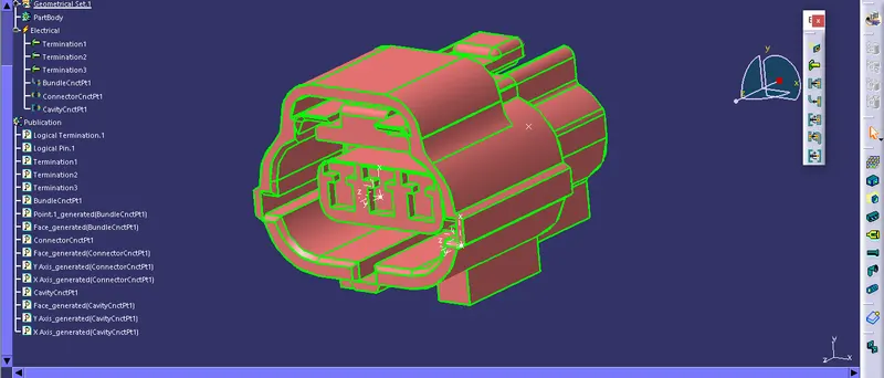
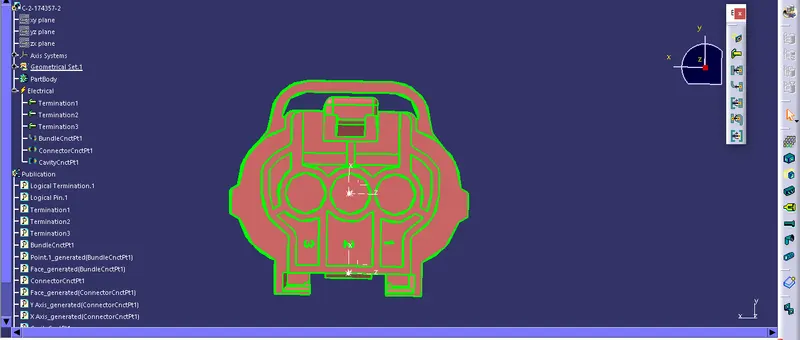
Create midpoint on the mating face of the connector and create an axis system as shown below by taking y-axis in the direction of mating face ,x -axis in the direction of lock side and z- axis in the direction perpendicular to x and y axis respectively.
Bundle connection point;
create a midpoint on the wire entry side of the connector
Switch to electrical part design workbench;
1 st step is to define the part as a connector and give no of terminations as shown below here for this part it is 3.
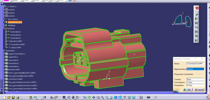
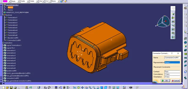
next step is to define bundle connection point and connector connection point as shown below,
- Deutsch DT06 – 08SA
Connector connection point;
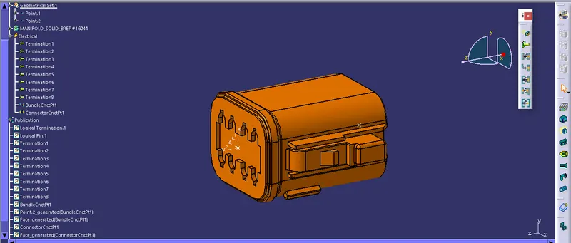
Create midpoint on the mating face of the connector and create an axis system as shown below by taking y-axis in the direction of mating face ,x -axis in the direction of lock side and z- axis in the direction perpendicular to x and y axis respectively.
Bundle connection point;
create a midpoint on the wire entry side of the connector
Switch to electrical part design workbench;
1 st step is to define the part as a connector and give no of terminations as shown below here for this part it is 8.
- Tyco 85229-1
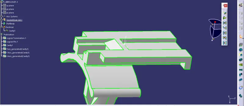
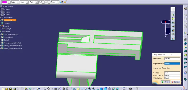
This is a connector clip here first we want to create a point on the connecting face and insert an axis system in that point and its orientation should be same as the connector to which it is connected after that switch to electriacal part design and define the part as mounting equipment and the define cavity connection point as shown below.
CONCLUSION
The connector is successfully modeled in CATIA V5 and the same is added to the catalog for further references.