Wiring harness design in CATIA V5 - 3D modeling Week 2 Challenge
- Create/Download Connector 3D - The 3D model of the connector is downloaded from websites or created manually.
- Create required Geometrical Parameters - The required geometrical parameters like Connector Point, Bundle Entry Point, Cavity Point, Connector Axis, Cavity Axis, etc are created.
- Define Part as Connector - We need to define the part as a Connector.
- Define Bundle Connection Points - The point where the bundle is connected to the connector is called Bundle Connection Point. We need to define the Bundle Connection Point.
- Define Connector Connection Points - The point where the connector is connected with this connector is called as Connector Connection Point. We need to define the Connector Connection Point.
- Define Cavity Connection Points (if any) - The point where the cavity is connected to the connector is called as Cavity Connector Point. We need to define the Cavity Connection Point.
Components:
1. Deutsch DT06 – 08SA
i. Download Connector 3D:
The 3D model is downloaded from the given link and save as a Catpart file.
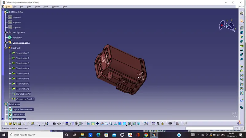
ii. Geometrical Parameters:
* Bundle Entry Point: The bundle entry Point is created at the rear part of the connector.
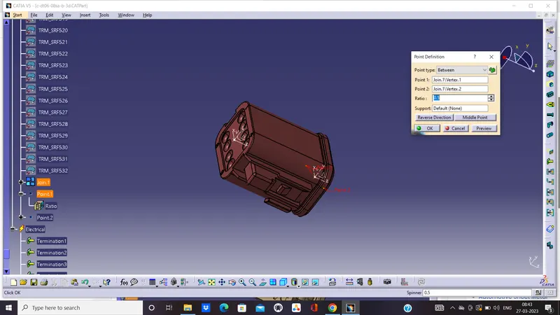
* Connector Point: The connector Point is created at the mating side of the connector.
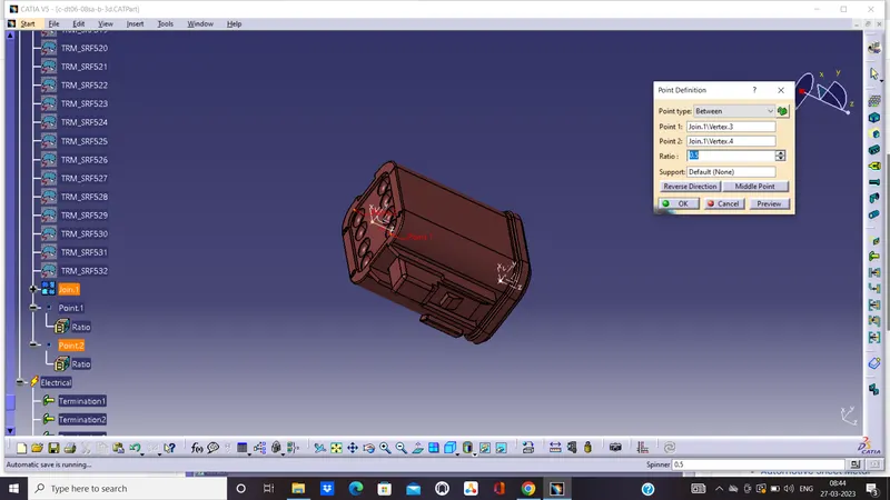
* Connector Axis: The connector axis is created with respect to Connector Point.
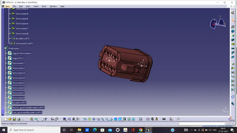
iii. Definition of Component:
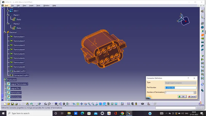
The component is defined as the connector using "Define Connector" tab in the "Electrical Part Workbench". The number of terminals is defined.
iv. Bundle Connection Point Definition:
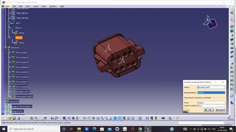
The bundle connection point is defined using "Bundle Connection Point Definition" tab in the "Electrical Part Workbench". The parameters are defined appropriately.
v. Connector Connection Point:
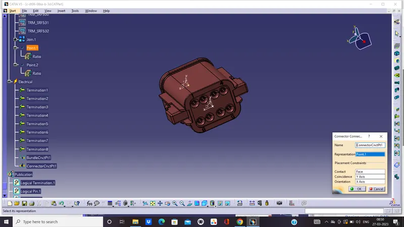
The connector connection point is defined using "Connector Connection Point Definition" tab in the "Electrical Part Workbench". The parameters are defined appropriately.
2. Tyco 174357-2:
i. Download Connector 3D:
The 3D model is downloaded from the given link and save as a Catpart file.
ii. Geometrical Parameters:
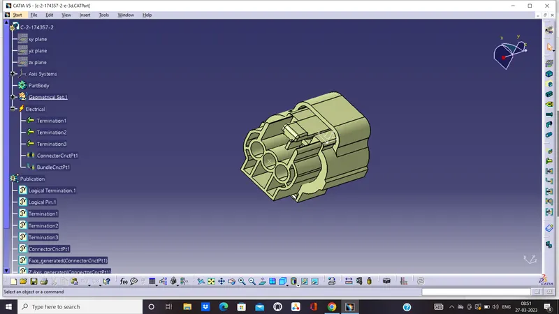
* Bundle Entry Point: The bundle entry Point is created at the rear part of the connector.
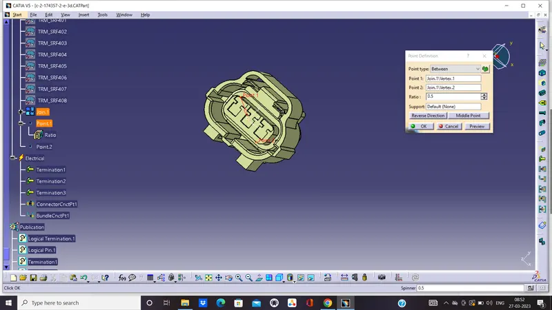
* Connector Point: The connector Point is created at the mating side of the connector.
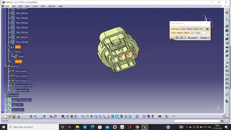
* Connector Axis: The connector axis is created with respect to Connector Point.
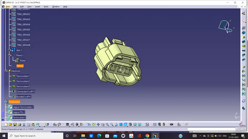
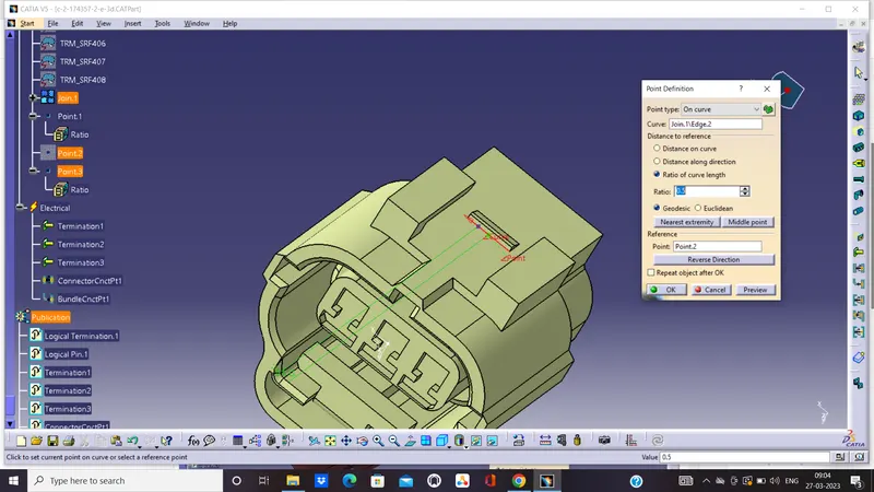
* Cavity Point: The Cavity Point is created at the cavity position of the connector.
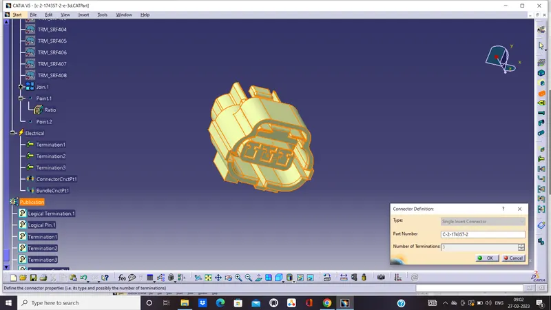
iii. Definition of Component:
The component is defined as the connector using "Define Connector" tab in the "Electrical Part Workbench". The number of terminals is defined.
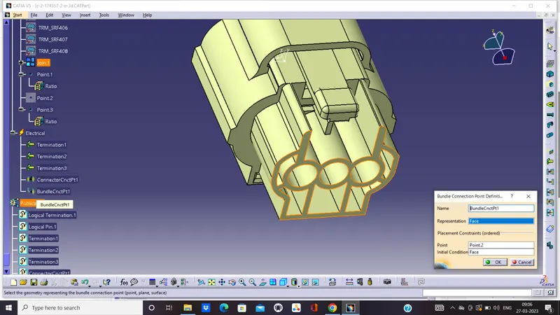
iv. Bundle Connection Point Definition:
The bundle connection point is defined using "Bundle Connection Point Definition" tab in the "Electrical Part Workbench". The parameters are defined appropriately.
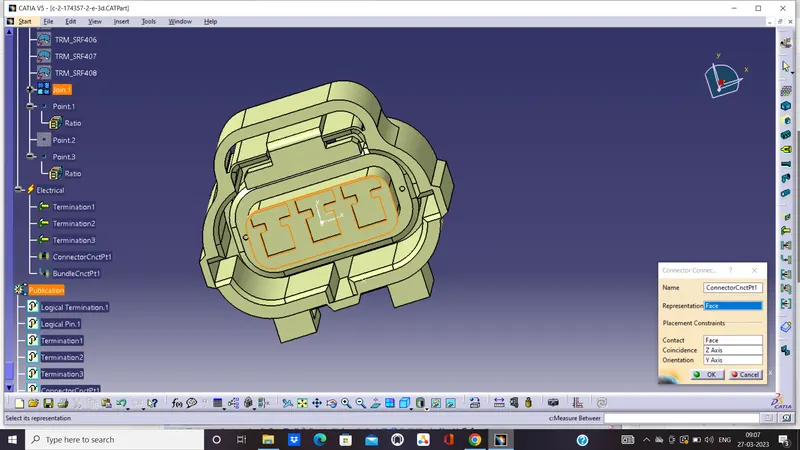
v. Connector Connection Point:
The connector connection point is defined using "Connector Connection Point Definition" tab in the "Electrical Part Workbench". The parameters are defined appropriately.
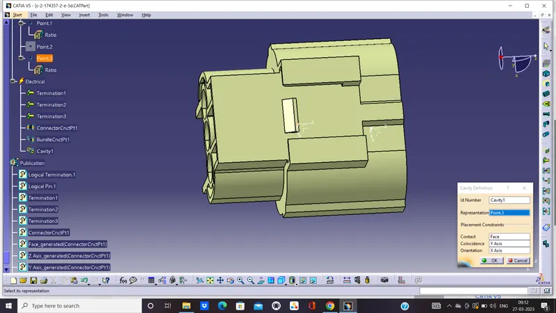
vi. Cavity Connection Point:
The cavity connection point is defined using "Cavity Connection Point Definition" tab in the "Electrical Part Workbench". The parameters are defined appropriately.
3. Tyco 85229-1
i. Download Connector 3D:
The 3D model is downloaded from the given link and save as a Catpart file.
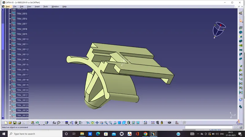
ii. Geometrical Parameters:
* Cavity Point: The Cavity Point is created at the cavity position of the connector.
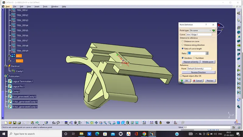
* Cavity Axis: The Cavity axis is created with respect to Cavity Point.
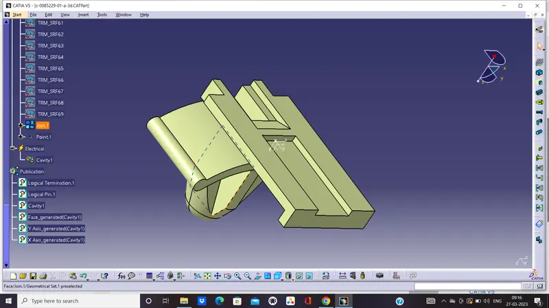
iii. Definition of Equipment:
The component is defined as equipment using "Define Equipment" tab in the "Electrical Part Workbench".
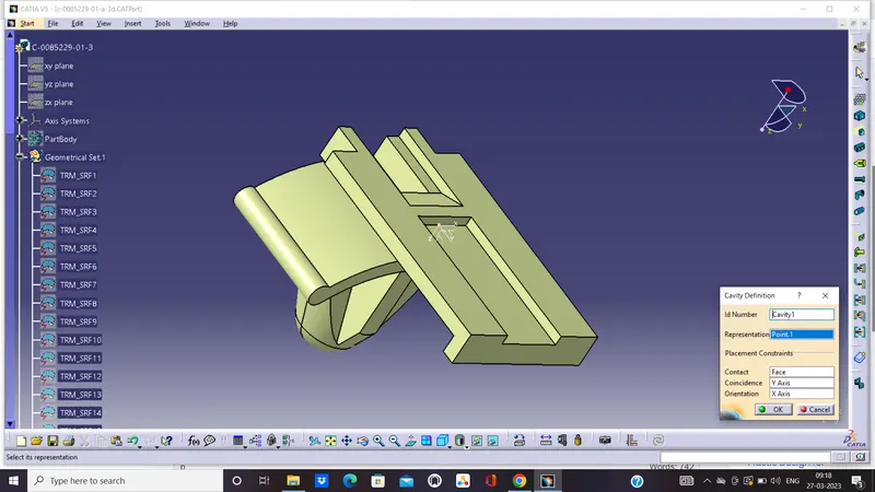
iv. Definition of Cavity & Cavity Connection Point:
The defined equipment is further defined as Cavity using "Define Cavity" tab in the "Electrical Part Workbench".
The cavity connection point is defined using "Cavity Connection Point Definition" tab in the "Electrical Part Workbench". The parameters are defined appropriately.
Creation of Catalogue:
i. Creating Catalogue File:
A new catalogue file is created using the tab File > New > "CatalogDocument".
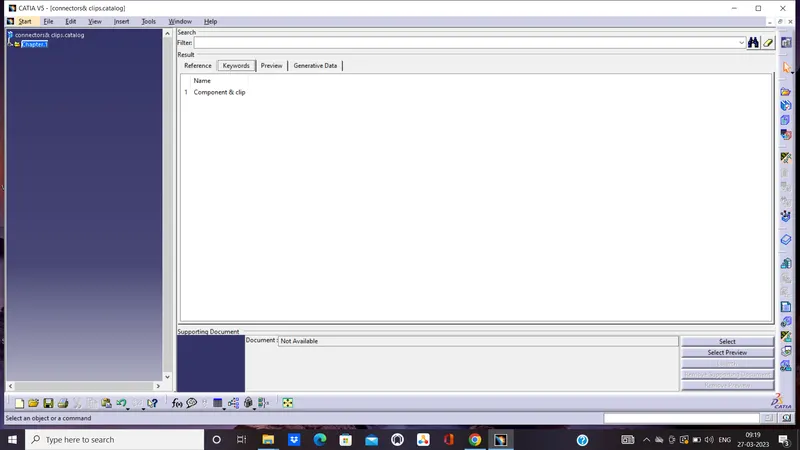
* Add Family: A new family of components is added using the "Add Family" tab. The name is given and the type is chosen as "Electrical"
ii. Add Components into Catalogue:
To add the components to Catalogue, "Store book" tab from "Electrical Part Workbench" is used. The appropriate catalogue and family are chosen while adding the components.
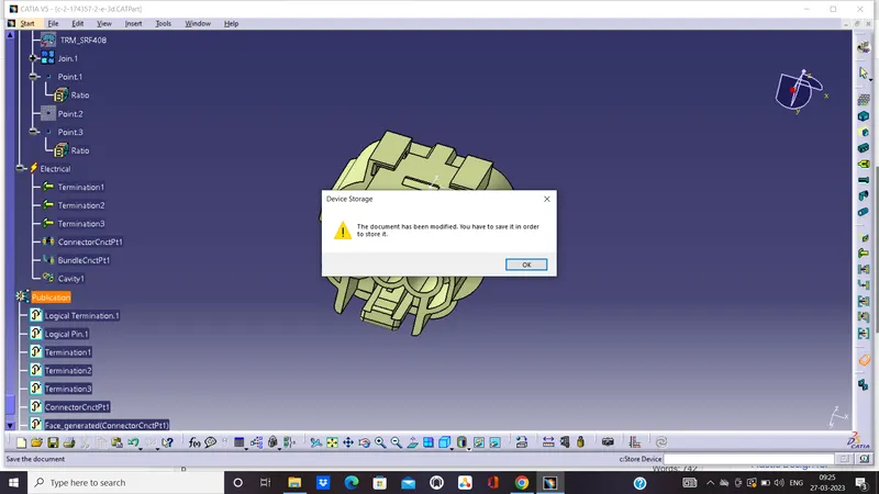
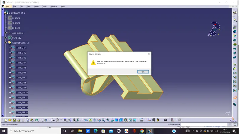
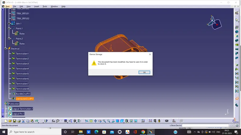
iii. Add Catalogue as favourite in Electrical Mapping:
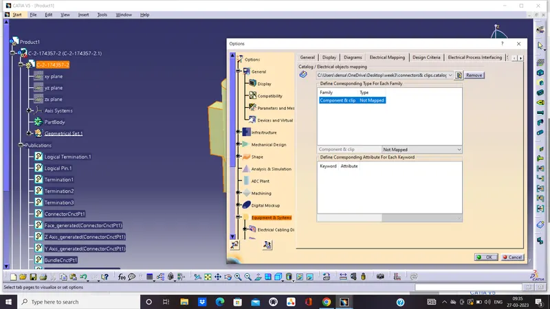
Thus created catalogue is then added into favourite by using the tabs, Tools > Options > Equipment & Systems > Electrical Harness Discipline > Electrical Mapping. In this window, click on "Add Favourite" tab and the desired catalogue from the folder and click "Ok".
Attachments:
The following are attached to this in a single Zip file.
- c-2-174357-2-e-3d.CATPart
- c-0085229-01-a-3d.CATPart
- c-dt06-08sa-b-3d.CATPart
- Product1.CATProduct
- Connectors & Clips.catalog