Week 8 - Challenge 4 - Bumper
Bumper DESIGN AND DRAFT ANALYSIS
Objective:
Create the Bumper Plastic component through the given Class-A surface. To begin with, the tooling axis for the given Class-A Surface should be created meeting the requirements of the draft angle and at the end perform the Draft analysis on the model.
Take the Thickness of the component to be 3 mm
Bumper:
A bumper is a structure attached to or integrated with the front and rear ends of a motor vehicle, to absorb impact in a minor collision, ideally minimizing repair costs. Stiff metal bumpers appeared on automobiles as early as 1904 that had a mainly ornamental function.
To design the Bumper first you need Class A Surface, if you have Class A Surface means you can create the tooling axis and do further design.
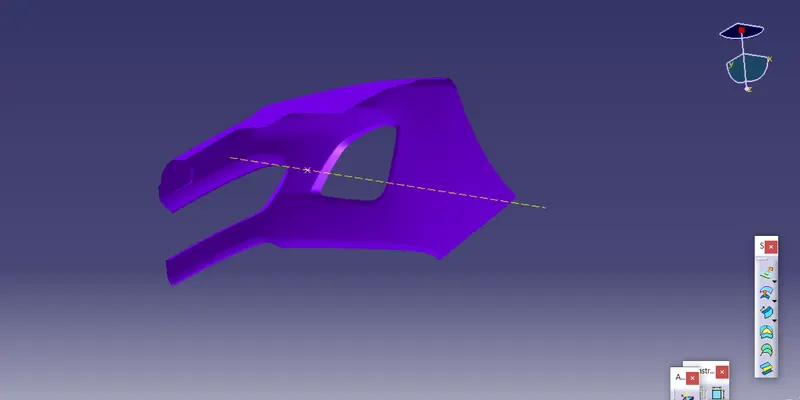
Given Class A Surface:
Class A surface is the outer most surface of the component, it is an aesthetic surface. It is also called as Strak. As a designer we don't have rights to modify the class A surface without permission.
Then we have check the class A surface whether it is joined or not by using boundry command if the boundry command shows only the the outer edges means we can work on class b otherwise we have to correct class A then only we can work on Class B.The above image is the Class A Surface. We can give different colors to identify the separate surfaces.
Tooling Axis:
Tooling axis is very important to design a product. It is nothing but the direction of the molds open close and whether it is moves in the x, y or z direction. First we have to decide which direction is probabily suitable for the particular product. Once we get the Cass A Surface, we can check the surface and able to create the tooling direction.
Procedure to Create the Tooling Axis:
- First we have to create a point on the flate face or circle midpoint to create a line.
- Once we created the point means we can create a line (Dummy axis) on the point in the suitable direction. We can find the suitable direction by simply see the object from x,y and z directions. If the object is fully visible from one of the direction means that is the line direction.
- After finding the direction just create a dummy axis and axis system.
- Then intersect the part with yz plane and create an bisecting line using the side angular lines which might create a problem.Do the same step in the xy plane to create an another line.
- After creating the two line which might create a problem, then draw a biseting line using the two bisecting line that we drawn from the yz and xy plane.
- In this Bumper we can select any point in the x direction becasue from x direction only we can able to see the hole structure. Here we can also use other tooling axis creation method by using the center of gravity point.
Draft Analysis:
Draft: Draft is used to remove the component fom the core and cavity. It will reduce the wear in component and molds so the the life of core and cavity will increase.
Draft Analysis: The Draft Analysis allows the user to easily analyze a part for proper draft angle. A Draft Angle describes the amount of taper for molded or cast parts perpendicular to the parting line.
The minimum draft angle ranges between 0.5 o 3 degree. Mostly 3 degree angle is widly used to make many components.
Draft: Draft is used to remove the component fom the core and cavity. It will reduce the wear in component and molds so the the life of core and cavity will increase.
Draft Analysis: The Draft Analysis allows the user to easily analyze a part for proper draft angle. A Draft Angle describes the amount of taper for molded or cast parts perpendicular to the parting line.
The minimum draft angle ranges between 0.5 o 3 degree. Mostly 3 degree angle is widly used to make many components.
Class A Draft Analysis:
Procedure to do Draft Analysis:
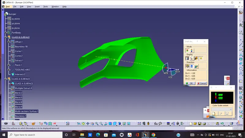
- Once we created the tooling axis means we can do draft analysis. First we have to switch the view mode to shading with material.
- After switching to shading with material mode we can now click draft analysis tool. Then we have to place the compass on the tooling axis by clicking and draging the compass red dot.
- After placing the compass lock the direction and click the surface to do draft analysis.
-
From the above image we can see that the green area has the draft angle above 3 degree. Here their is no blue or red color in the surface if their is any blue color surface means the draft angle ranges between 0 to 3 degree. If the color is red means negative or below 0 degree. We can change the color and angle value by clicking the color and values. But green,blue,red are standard colors.
Final Plastic Component Draft Analysis:
-
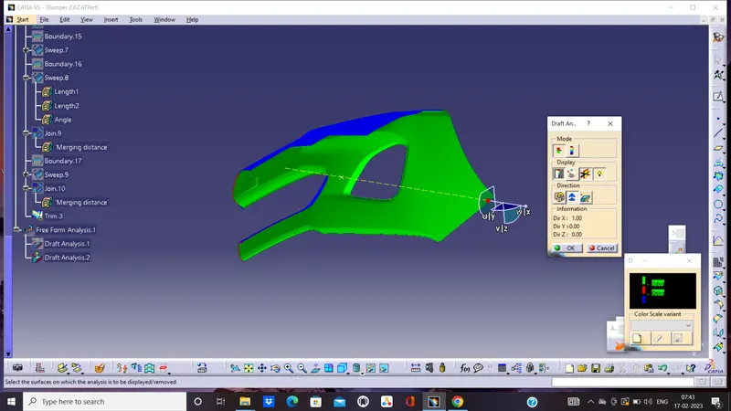
Here also we are using the same methods that we followed in class A draft analysis but instead of class surface we are choosing Final P
-
From the above image we can see that the plastic component is clearing the darft analysis so that itpossible to manufacture this part. The green area has more than 3 degree angle so it is posible to eject the component from the mold without sticking to mold. If we zoom closely we can see a blue color line on the edge that means the draft angle ranges between 0 to 3 degree but the actual degree is 2.9 degree we can check the individual spot degree by using analyses under the running point tool in the display of the draft tool.
Class B Surface Creation:
Class B Surface is the inner surface it can be created by using the class A surface by using several surface features.
Basic Features used in Class B Creation:
- Offset
- Exract
- Trim
- Exrapolate
- Radius
- Sweep
- Join
- Multisection
- Extrude etc.,
First, we can directly offset the class A surface then we can correct the errors occured in the offset.
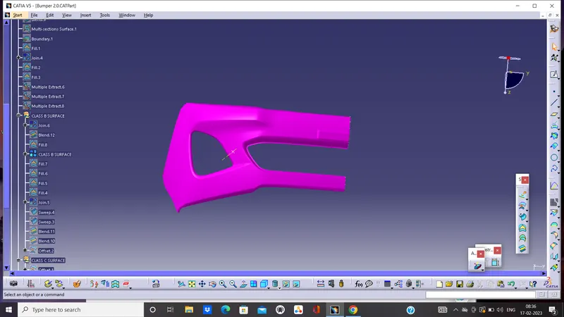
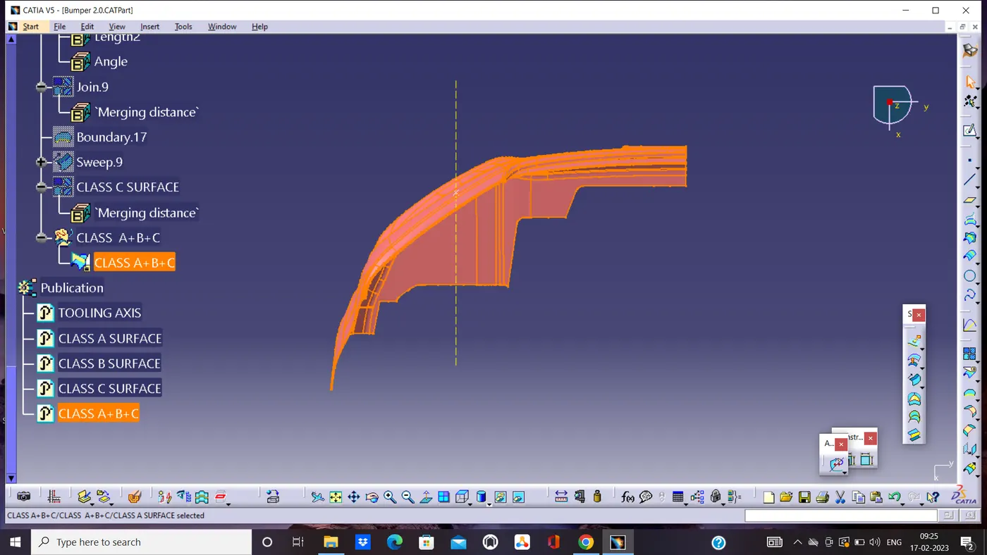
Class C Surface Creation:
The surface which is used to clo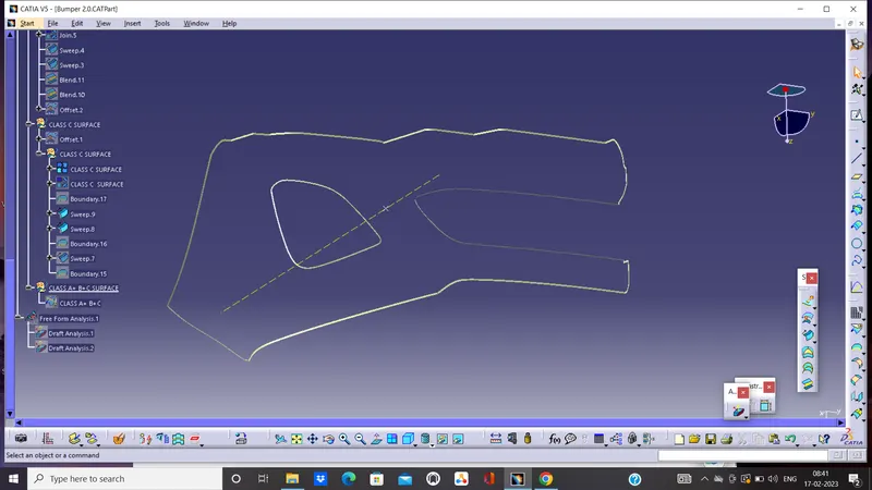 se the class A and clas B surface is called class C surface. Simply it gives thickness to the component. We can create the surface using the features mentioned in the below image or other features.Here I used reference with surface sweeep command to create the class C surface.
Class A+B+C Surface: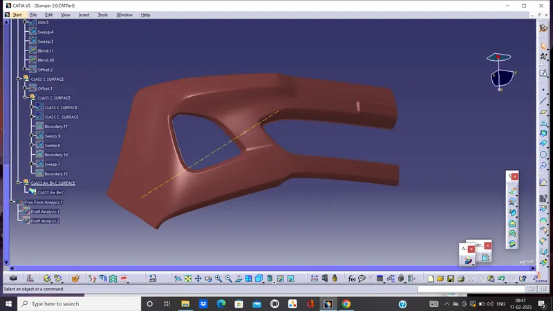
After the creation of all three surfaces we can join them together with join command.
Solid Plastic Component:
We created only surfaces but we need solid part, so after the creation of all surfaces we should do close surface from part workbench. Finally the Coin Holder Design is ready for manufacturing.
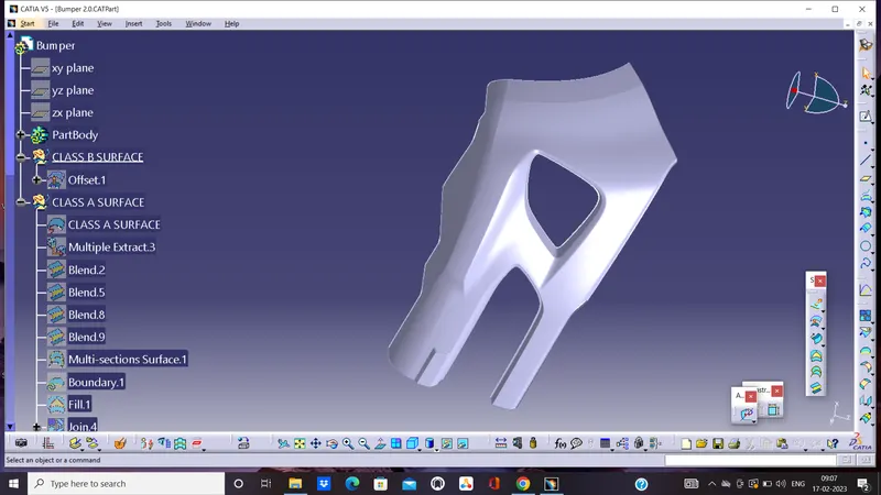
Publications:
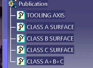
Solid model with the proper color code of the draft angle in various orientations (Isometric, Front, Side, and Top View):