Wiring harness design in CATIA V5 - 3D modeling Week 2 Challenge
WIRING HARNESS DESIGN IN CATIA V5 - 3D modeling
Aim: To download the connectors & Connector clip cad data from given link & define it as Electrical Connector using Electrical Part design Workbench and to define all the necessary properties to Connectors & Clip.
Connectors
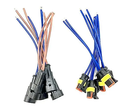
An electrical connector is an electromechanical device used to create an electrical connection between parts of an electrical circuit, or between different electrical circuits, thereby joining them into a larger circuit. Most electrical connectors have a gender – i.e. the male component, called a plug, connects to the female component, or socket. The connection may be removable (as for portable equipment), require a tool for assembly and removal, or serve as a permanent electrical joint between two points. An adapter can be used to join dissimilar connectors.
Electrical Part Design Workbench
Deutsch DT06 – 08SA
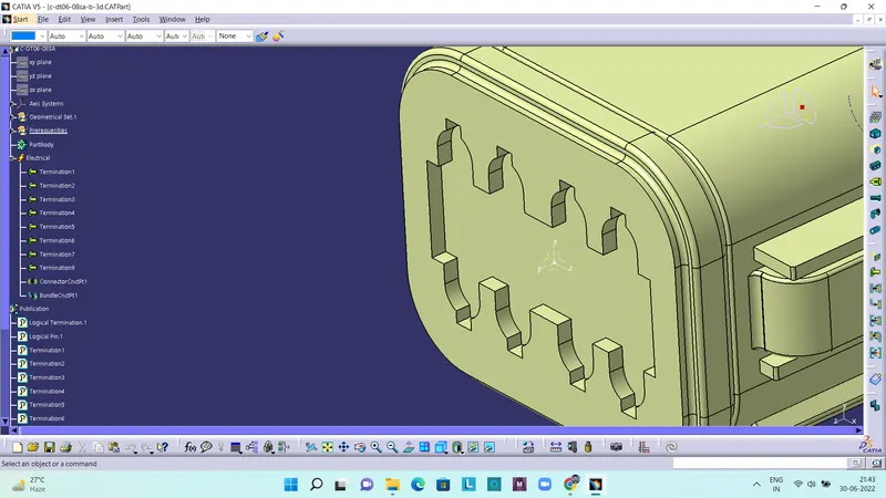
The above picture shows a Deutsch DT06 – 08SA connector. Here the connector connection points have been defined with the help of points and axis systems.
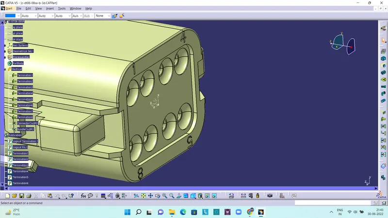
The above picture shows defining of bundle connection point. This is created with the help of points and axis system, and also the orientation of the axis system should be same as the first definition. That is the axis systems should be same through out all the connectors and clips.
Tyco 174357-2
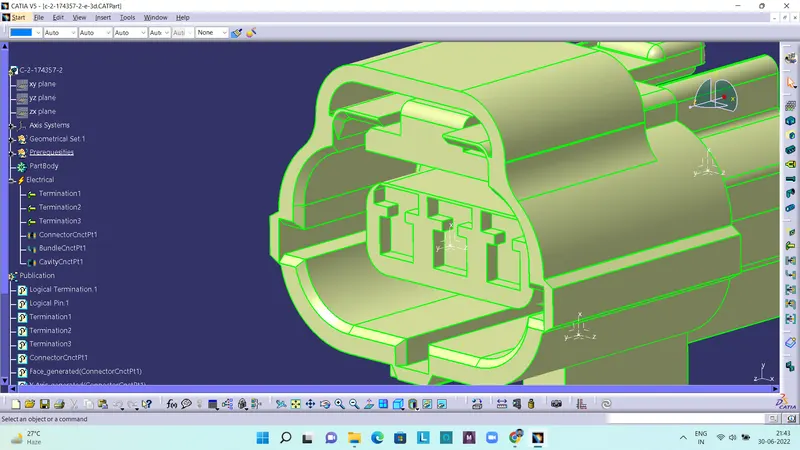
The above picture shows a Tyco 174357-2 connector. Here also the connector connection points have been defined with the help of points and axis systems, inorder to connect the other connector with it.
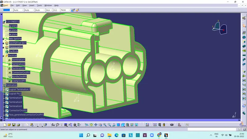
The above picture shows defining of bundle connection point, inorder to connect bundle with the connector. This is also created with the help of points and axis system, and also the orientation of the axis system should be same as the first definition.
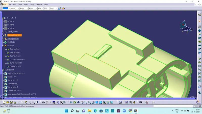
The above picture shows defining the cavity connection point. It is done inorder to connect the connector to a mounting element (clips). This is also created with the help of points and axis system, and also the orientation of the axis system should be same as the first definition.
Tyco 85229-1
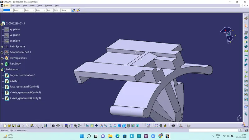
The above picture shows a Tyco 85229-1 clip, which is used as a mounting element to mount a connector on it. Here the cavity is defined with the help of points and axis system, and also the orientation of the axis system should be same as the first definition.
Electrical Assembly Design Workbench
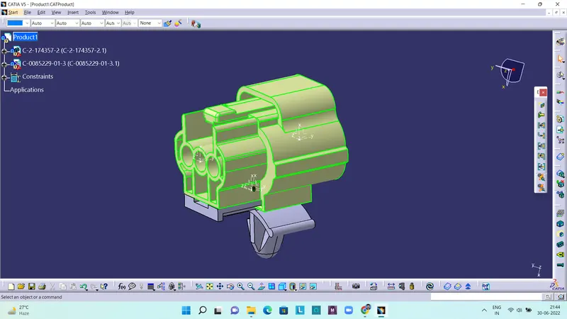
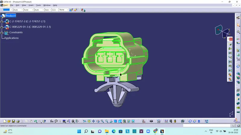
Here the connector and clip is assembled in electrical assembly design workbench. It is done with the help of a command called Connect electrical devices.
Other View: