Wiring harness design in CATIA V5 - 3D modeling Week 2 Challenge
Connector-Male
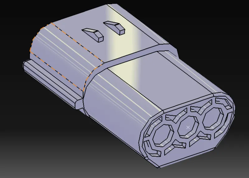
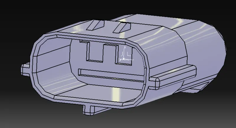
Step.1 :
Making connector connection point
A midpoint was created on the face that was supposed to be normal to the bundle entry.
Step.2:
axis system was created on the point according to the standard.
Step.3:
Making the bundle connection point.
Midpoint was created and an axis system was created on it
Step 4:
In the electrical part design, the part was defined as connector.
Step 5;
The connector connection point and Bundle connection point were defined.
Connector-Female:
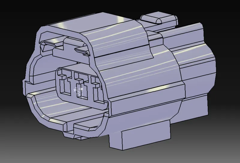
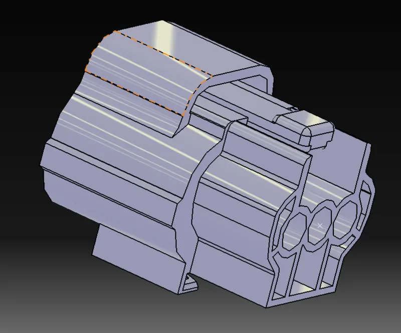
Making connector connection point
A midpoint was created on the face that was supposed to be normal to the bundle entry.
Step.2:
axis system was created on the point according to the standard.
Step.3:
Making the bundle connection point.
Midpoint was created and an axis system was created on it
Step 4:
In the electrical part design, the part was defined as the connector.
Step 5;
The connector connection point and Bundle connection point were defined.
Mounting Clip:
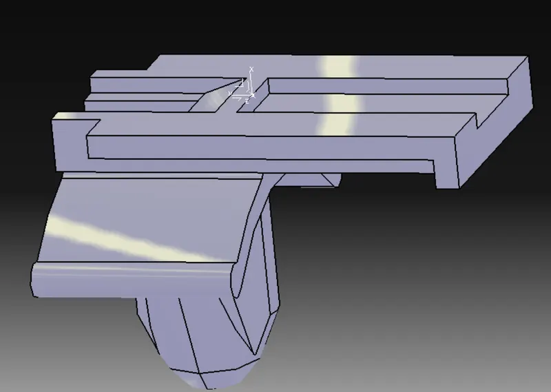
Step 1: Midpoint was created.
Step 2: A cavity connection point was created.
Step 3: Axis system was made on the point and the orientation was made the same as the one that of the connector.
Step 4: In the electrical part design, the part was defined as mounting equipment.
Step - The cavity connection point was defined.
Assembly
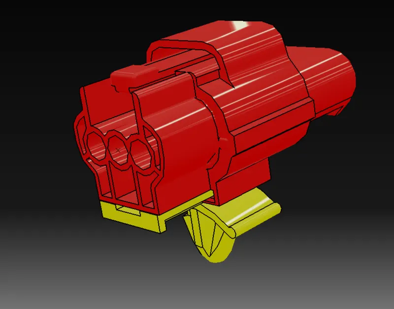
The Connector-Female and Mounting clip was imported and connected using Electrical Connection Point.
Then Connector-Male was imported and it was connected to the Connector(female) using the Electrical Connection Point.