Wiring harness design in CATIA V5 - 3D modeling Week 2 Challenge
WIRING HARNESS.
AIM:
To define the Electrical properties of the given components.
OBJECTIVE:
To download the above CAD data of the parts from the given source.
To define the Electrical properties correctly.
To create a catalog of the components so that they can be used later.
SOLUTION METHODOLOGY:
First a new 'catalog document' is created and then add family is selected to add the group to the catalog document.
The name of the family is given as the 'connectors' and the catalog document is saved in the desired folder.
After defining the electrical properties, the components are saved in the catalogs so that they can be used in the feature without again defining the electrical properties.
PART - 1: DEUTSCH DT06 - 08SA:
Step - 1:
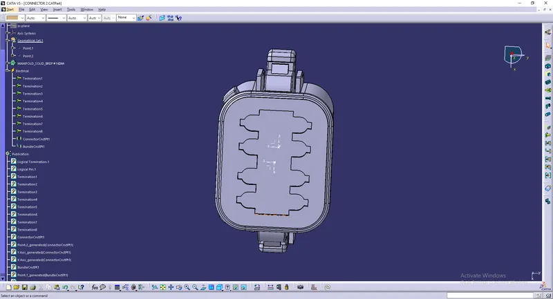
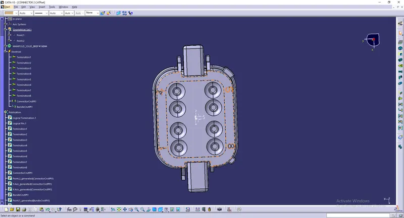
To identify the Connector Side and the Bundle Side.
CONNECTOR SIDE:
BUNDLE SIDE -
Step - 2:
To create a mid-point on the bundle side in the Part Workbench to define the Bundle connection properties.
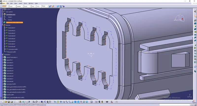
Step - 3:
To create a mid-point at the Connector side in the Part Workbench.
To create an axis system through the point.
Define the axis as:
X-axis - Towards the locking side
Y-Axis - Normal to the connector face
Step - 4:
Go to the Electrical Part Design Workbench to define the Connector connection point and Bundle connection point.
Step - 5:
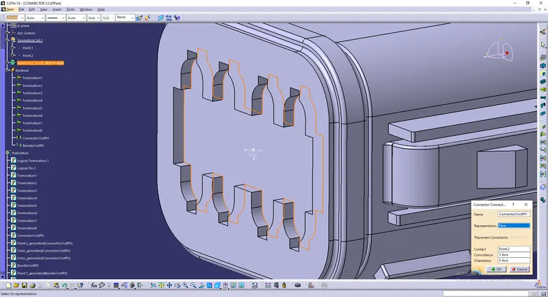
First, define the Connector and the number of Termination.
Then define the Connector Connection Point.
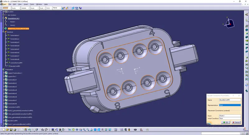
And then define the Bundle Connection Point.
Connector Connection Point -
Bundle Connection Point -
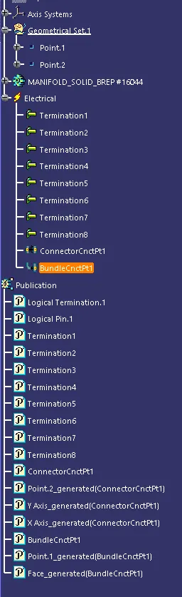
TREE STRUCTURE:
Step - 6:
Now save the part and add the part to the Catalogue created for the connectors so that it can be used later.
PART - 2: TYCO 174357 - 2:
Step - 1:
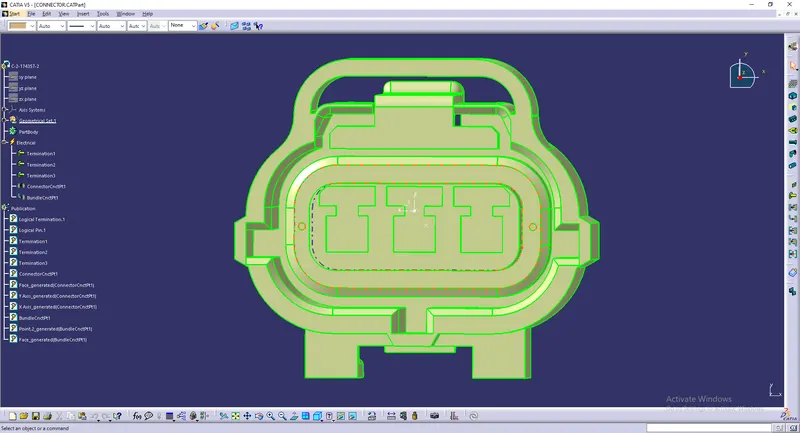
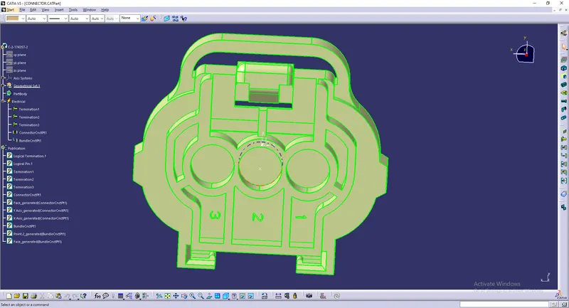
To identify the Connector Side and the Bundle Side.
Connector Side -
Bundle Side -
Step - 2:
To create a mid-point on the bundle side in the Part Workbench to define the Bundle connection properties.
Step - 3:
To create a mid-point at the Connector side in the Part Workbench.
To create an axis system through the point.
Define the axis as:
X-axis - Towards the locking side
Y-Axis - Normal to the connector face
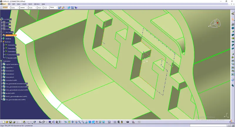
Step - 4:
Create a point for the Mounting clip at the required cavity position and create an axis system through the point for the cavity clip.
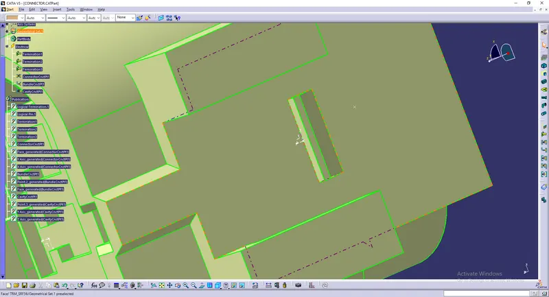
Step - 5:
Go to the Electrical Part Design Workbench to define the Connector connection point and Bundle connection point.
Step - 6:
First, define the Connector and the number of Termination.
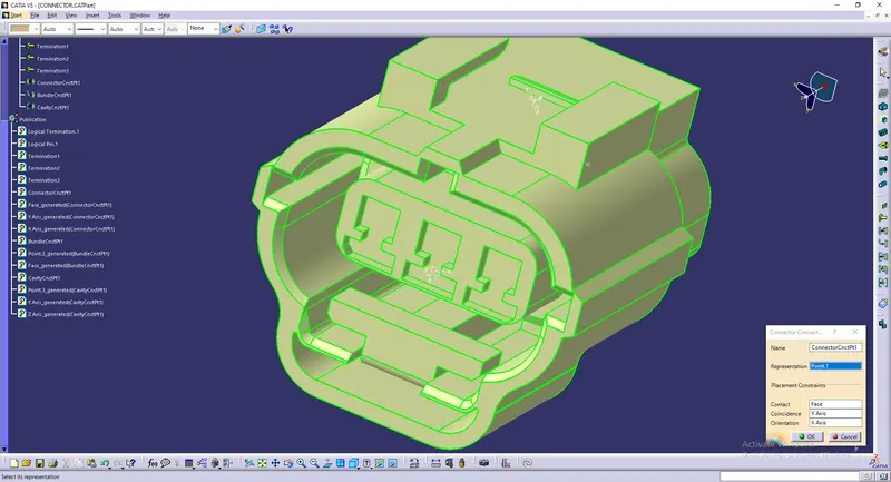
Then define the Connector Connection Point.
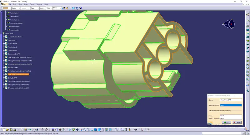
And then define the Bundle Connection Point.
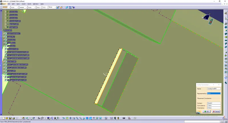
And then define the Cavity Connection point.
Connector Connection Point -
Bundle Connection Point -
Cavity Connection Point -
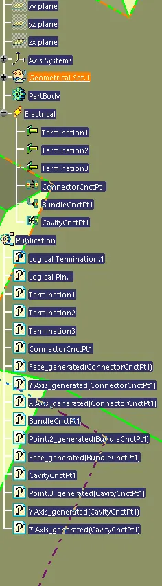
Feature Tree -
Step - 7:
Now save the part and add the part to the Catalogue created for the connectors so that it can be used later.
PART - 3: TYCO 85229 - 1:
Step - 1:
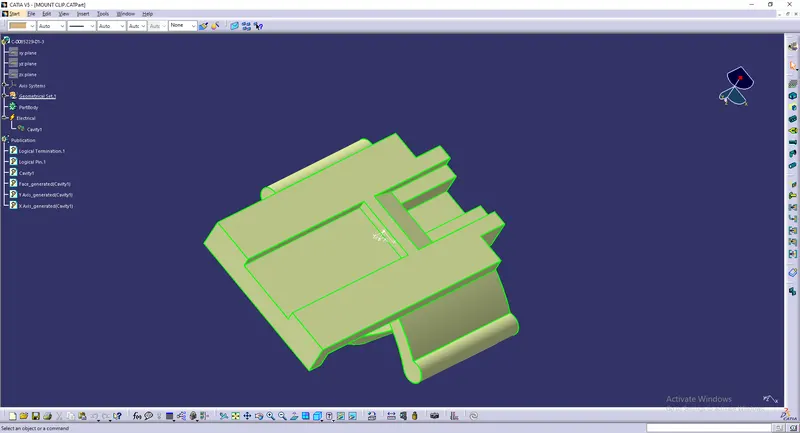
Create a mid-point at the location where the mounting equipment will be fitted with the connector.
Step - 2:
Create an axis system through the point.
Define the axis as per the orientation defined in the connector in which the mounting equipment will be assembled.
Step - 3:
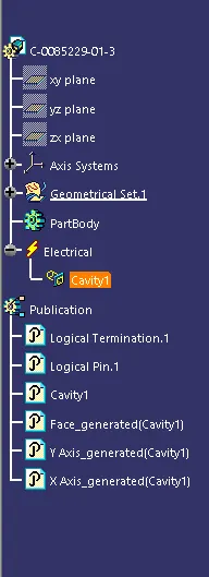
Go to the Electrical Part Design Workbench to define the electrical properties.
Define the object as the Mounting equipment.
Then define the same as a cavity.
CAVITY DEFINITION:
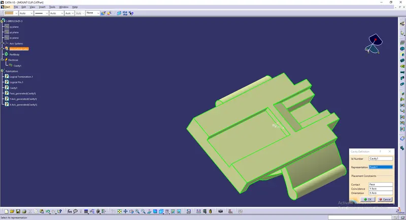
Feature Tree -
ELECTRICAL ASSEMBLY OF PART 1 AND PART 2:
As all the Electrical properties have been correctly defined so we can just bring the components to the Electrical Assembly Workbench, align them and use the option Connect Electrical Devices and select the components.