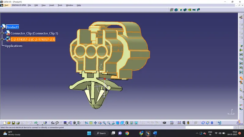
Wiring harness design in CATIA V5 - 3D modeling Week 2 Challenge
Wiring harness assembly structure – connector definition
- Create/download connector 3D
- Create required geometric parameters
- Define parts as a connector
- Define “bundle connection point”
- Define “connector connection point”
- Define “cavity connection point”
CONNECTOR DEFINITION IN CATIA V5
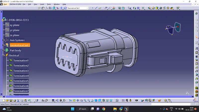
1.0 Deutsch DT06 – 08SA
- Create a mid-point in the contact face
- Create an axis system with respect to the create mid-point and define an axis direction
- Switch to electrical part design
- Define part as connector
- Define bundle connection point
- Define connection point
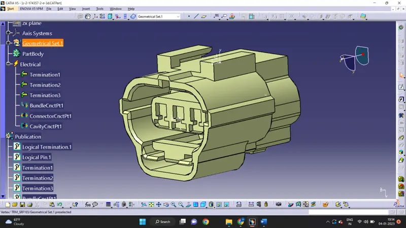
2.0 Tyco 174357-2:
- Create midpoint
- Create a Connector connection point
- create a Connector connection axis system
- create a cavity connection point
- create a cavity connection axis system
- Switch to an Electric part design and define the part as the connector
- Define Connector connection point and cavity connection point
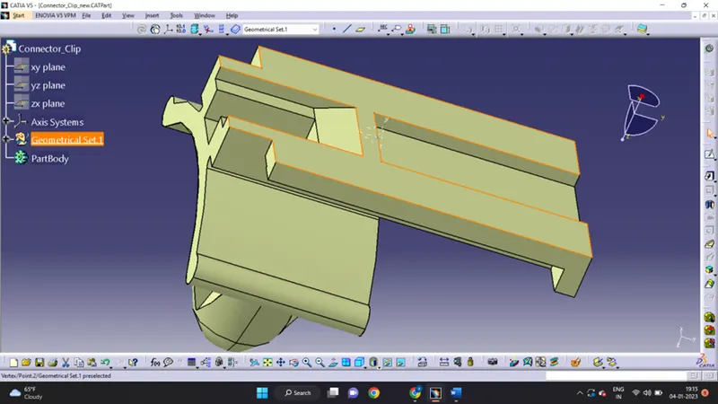
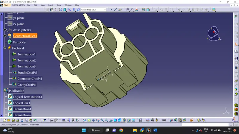 3.Tyco 85229-1:
- Create midpoint
- create cavity connection point
- create cavity connection axis system and orientation should be same as in connector
- Switch to Electric part design and define part as Mounting Equipment
- Define cavity connection point
Elctrical Assembly Design
- Import Connector and cavity/mounting clip.
- Select Defining Electric connection
- select cavity and then connector