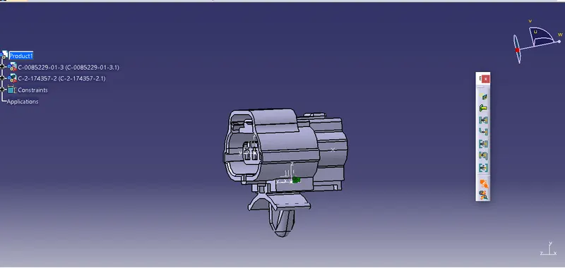
Wiring harness design in CATIA V5 - 3D modeling Week 2 Challenge
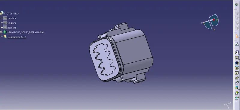
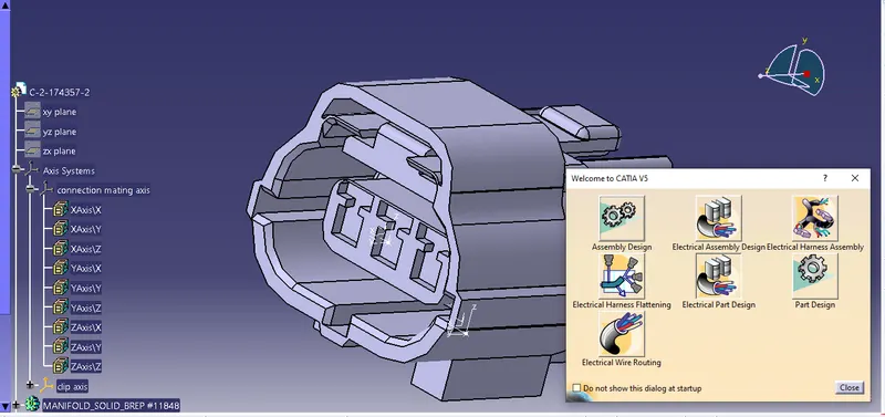
1. Open the stp file in catia
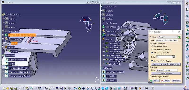
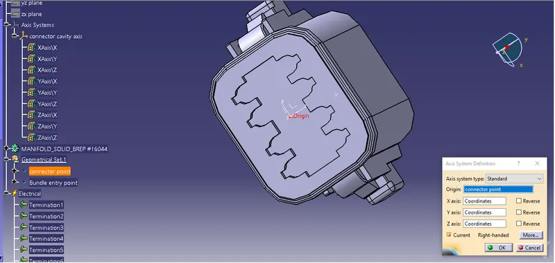
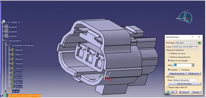
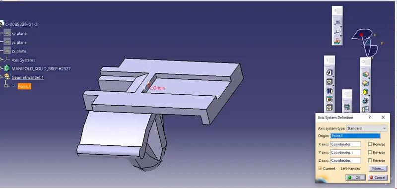
2. Creating geometry parameters. (connector connection point, connector cavity axis, bundle entry point)
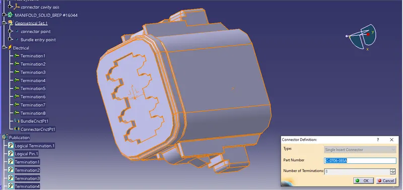
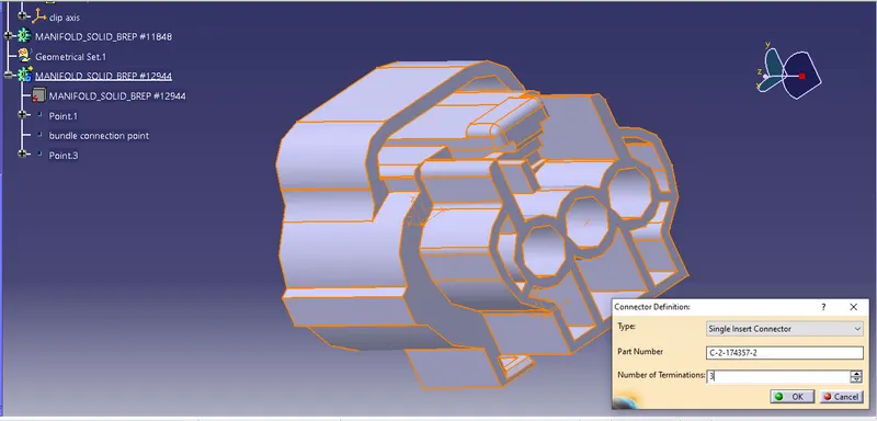
3. Defining part as connetor.
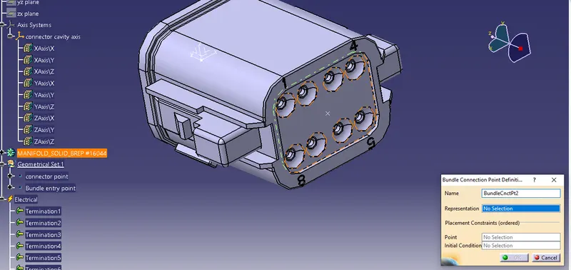
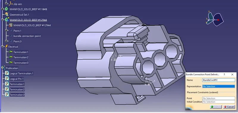
4. Defining bundle connection point.
Representation : FACE
Point : bundle connection point
Initial condition : FACE(normal to the direction of wire)
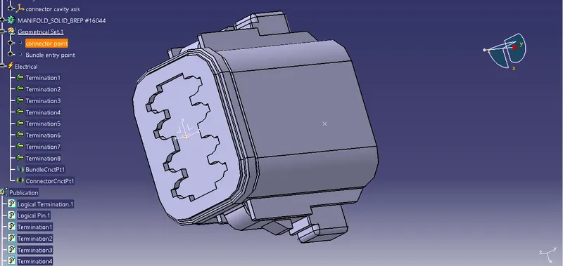
5. Defining connector connecton point.
Representation : POINT
contact : FACE
coincidance : Y AXIS
orientation : X AXIS / Z AXIS
 ====================================================================
1. Open the stp file in catia
2. Creating geometry parameters. (connector connection point, connector cavity axis, bundle entry point)
3. Defining part as connetor.
4. Defining bundle connection point.
Representation : FACE
Point : bundle connection point
Initial condition : FACE(normal to the direction of wire)
5. Defining connector connecton point.
Representation : POINT
contact : FACE
coincidance : Y AXIS
orientation : X AXIS / Z AXIS
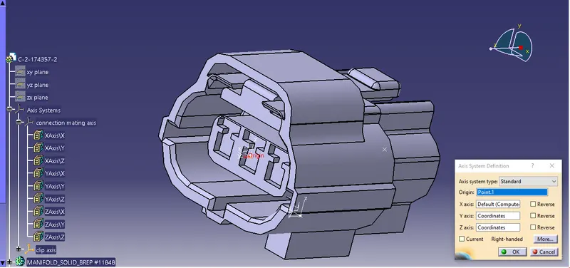
6 Defining cavity connection point.
Representation : POINT
contact : FACE
coincidance : Y AXIS
orientation : X AXIS / Z AXIS
====================================================================
Electrical assemble design :
connect electric design.