Wiring harness design in CATIA V5 - 3D modeling Week 2 Challenge
WIRING HARNESS ASSEMBLY STRUCTURE - CONNECTOR DEFINITION :
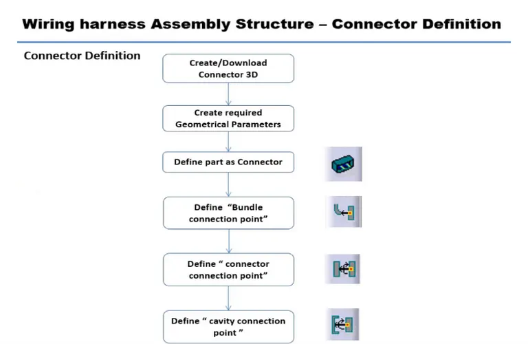
CONNECTOR DEFINITIONS IN CATIA V5 :
- Deutsch DT06-08SA :
Connector Mating Side:
Create midpoint on the contact face of mating side of Connector in Mechanical Part Design
Wire Bundle Entry Side:
- Create midpoint on the contact face of wire bundle entry side as per the image.
- Define the part as electric part.
Define as Electric Part:
- Choose ‘Electric Part Design’ workbench.
- Define the part as CONNECTOR in this workbench & give name of part and number of terminals as 8 according to image.
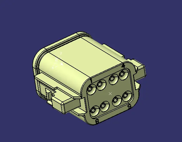
- Tyco 174357-2 :
Bundle Connection Point :
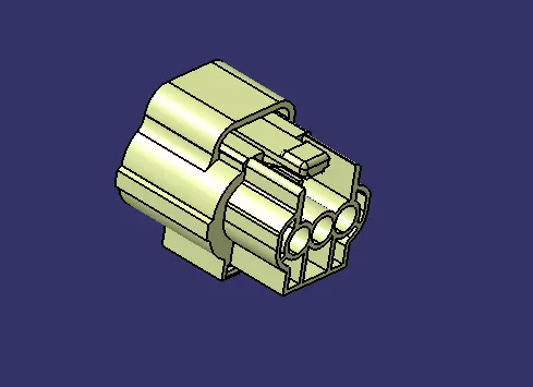
- Create a point on mating face and insert a new axis system.
- Define Cavity Connection Point by selecting the given point, face and Y & X axis as shown in figure
- Tyco 85229-1 :
Cavity :
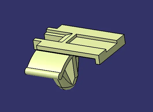
- Create a point on mating face and insert a new axis system by comparing it with the mating Connector.
- Define Cavity Connection Point by selecting the given point, face and Y & X axis as shown in figure
CREATION OF CONNECTOR & CLIP ASSEMBLY
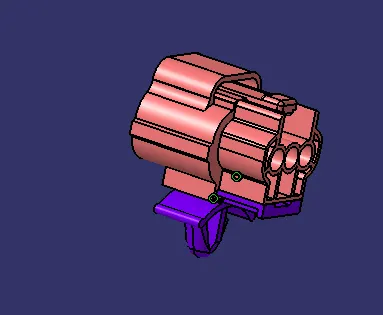
- Import Connector and Connector clip to a new assembly file. Arrange both parts as per required orientation.
- Go to Electrical Assembly Design
- Use Connect Electric Connection.
- First choose Clip and then Connector.
- Both will automatically connected as per given constraints