Wiring harness design in CATIA V5 - 3D modeling Week 2 Challenge
AIM:
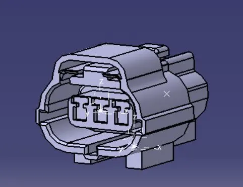
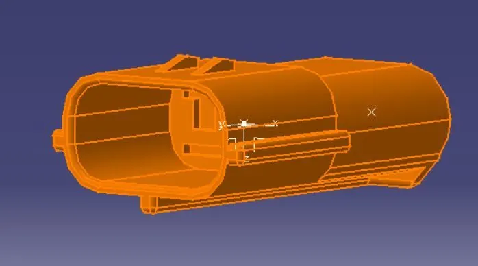
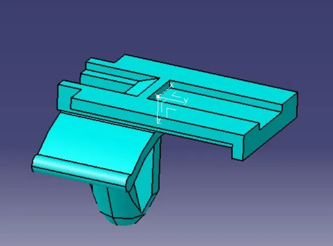
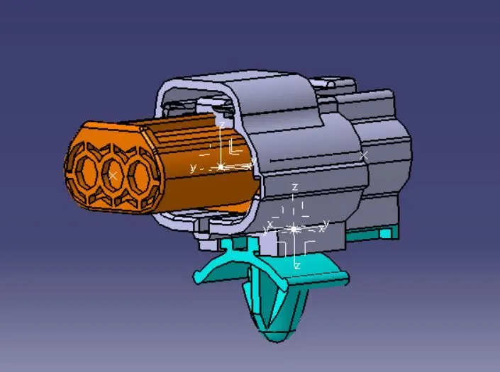
Download following connectors & Connector clip cad data from given link & define it as Electrical Connector using Electrical Part design Workbench. Define all the necessary properties to Connectors & Clip.
 |
|
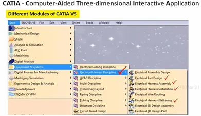
Important workbenches in CATIA V5. |
the important workbenches that are required for the mechanical wiring harness routing.
 |
|
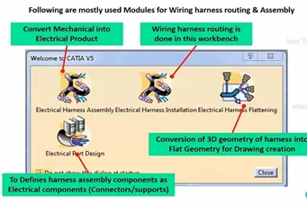
Definitions of electrical workbenches in CATIA V5. |
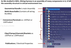
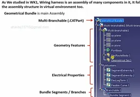
shows the feature tree that has to be followed while developing the wiring harness routing.
 |
 |
|
Feature tree in electrical workbenches in CATIA V5. |
|
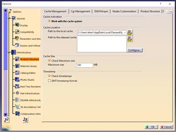
shows the changes that has to be made in cache management. In working with large amount of data in order not to lose any data and open the workbenches quickly, work with cache system option is toggled on. The information from other departments can be easily open when this option in activated.
 |
|
Changes to be made in cache management. |
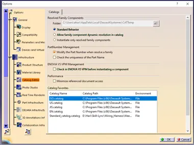
The catalog is a part storing document in which the parts which are frequently used in the modelling are stored and retrieved whenever it is required and at any location.
 |
|
Changes to be made in catalog editor. |
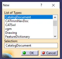
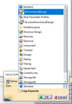
To create a new catalog, Go to New, select the catalog document. In catalog document create a family by using the add family option from Insert.
  |
|
To create catalog in catia. |
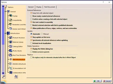 |
|
Part infrastructure options. |
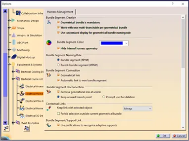 |
|
Electrical Harness management settings. |
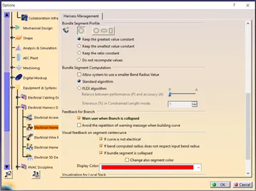 |
|
Electrical Harness management settings. |
Shows the part infrastructure options that has to be toggled on/off before starting the wiring harness in CATIA.
shows the electrical harness settings that has to be changed before starting the project.
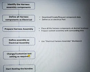 |
|
Design process for wiring harness routing of automotive vehicle. |
ELECTRICAL PART DESIGN
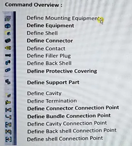
Command overview
 |
|
Command overview of wiring harness routing. |
shows the different electrical harness routing commands that are available in the electrical part design workbench.
 |
|
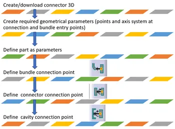
Connector definition. |
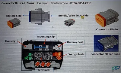
shows the Connector definition and the detailed process. Fig 16 shows the different connector parts.
 |
|
Connector parts. |
Geometry Parameters – Points and co-ordinate system (axis).
Connector connection points – This point is used for the connection of one connector to another connector.
Harness bundle entry point – This point defines where the harness bundle segment point will end when routed to the electrical connector.
Cavity connection point (optional): This point is used to define the connection of a connector to a connector clip. This only applies to connectors which have the mounting feature for a connector clip.
 |
|
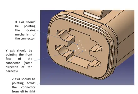
Connector axis system definition. |
Once the bundle and connector entry points and axis system are created in part design workbench as shown in Fig. 17, switch to electrical part design workbench. In electrical part design workbench click on Define Connector option and click the connector and enter the type, name and number of terminations.
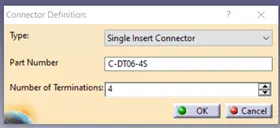 |
|
Connector Definition. |
Change the termination names as 1,2,3,4 as given in the part.
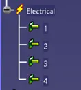 |
|
Termination name changed to 1,2,3,4. |
Now give the bundle connection point definition by clicking Define Bundle Connection and give the details as given in Fig. 20.
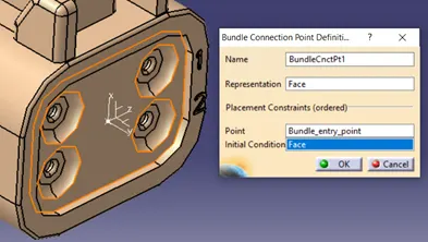 |
|
Bundle definition. |
Now define the connector connection point definition by clicking Define connector Connection and give the details as
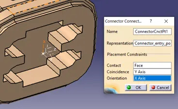 |
|
Connector definition. |
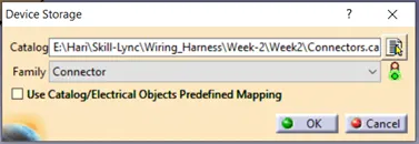
Add connector to catalogue. Click on store device command and select the connector catalogue that is already created and give type as connector and click on ok.
 |
|
Adding connector to catalogue. |
solution