Wiring harness design in CATIA V5 - 3D modeling Week 2 Challenge
Wiring harness design in CATIA V5 - 3D modeling Week 2 Challenge
INTRODUCTION
Wiring harness is the combination of electrical and mechanical CAD to connect all the electrical parts in the automotive at the optimum level.
BASICS OF ELECTRICAL DISTRIBUTION SYSTEM (EDS) AND WIRING HARNESS
1) Electrical Distribution System: It runs from front end to rear end of the vehicle. It involves physical and logical architecture schematic development, power distribution, wiring harness design, wiring harness component design of given electrical system. It ensures the physical location of all electrical components placed in the vehicle. It provides the logical connectivity between electrical components. It has electrical controller unit for different sections like Airbag ECU, ABS ECU, Engine (ECU).
2) E&E Architecture: It is the high-level logical connectivity diagram. It represents all the systems, sub-systems and logical connections between them. It shows the Control Area Network (CAN) between different electronic components.
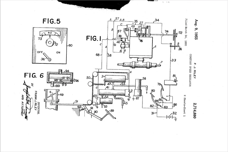
3) Logical schematics: Detailed design of E&E architecture. It shows the logical connectivity between different components and controls of given systema and subsystem. It does not define any other parameter except electrical connectivity.
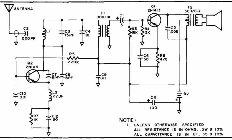
4) Electrical schematics: Detailed design of logical schematics, pin to pin connectivity, properties, fusing distribution, grounding distribution, interconnects, wire properties (wire gauge, color, type), circuit properties (circuit number, connector designation number, control device number), specification of components, end results of electrical core design of system and primary input for harness design.
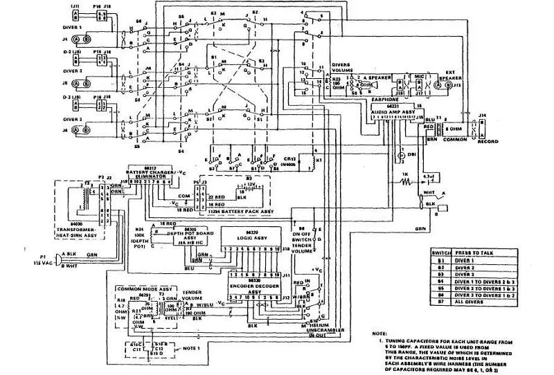
5) Wiring harness topology: Strategy to split the harness between different pieces to achieve the best manufacturability, serviceability and cost-effective design.
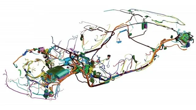
6) Wiring harness routing: It provides the desired path of wiring harness into given vehicle environment by applying set of design rules and industry best practices.
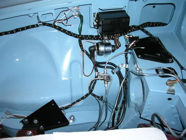
7) Wiring harness packaging: Fixing/mounting strategy of wiring harness routing to ensure the safe, reliable and durability of wiring harness by applying set of design rules and industry best practices.
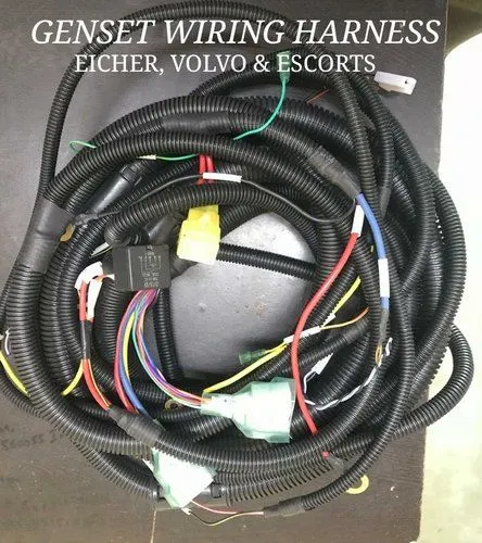
WIRING HARNESS ASSEMBLY
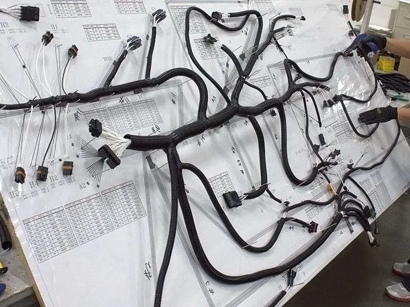
The term Wiring Harness refers to the assembly of
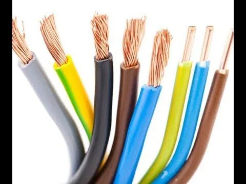
1) Wires: Various bundled wires together. Each individual wire is responsible for carrying the electrical signals and energy. Wires are made up of Cu conductors insulated with PVC insulation.
CONNECTOR MODELING
Download the specified connector from te.com. In the part design workbench provide the center point and axis system to the wire inserting end and connection end. The axis must be given in a specified way:
X-axis: Towards the clamp
Y-axis: Towards the connection
Z-axis: left or right of the connector.
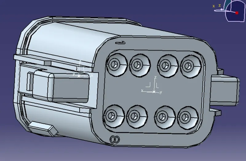
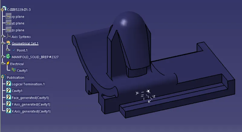
- THE CONNECTOR IS FIRST UPLOADED IN THE PART DESIGN WORKBENCH
- WE DEFINE THE POINTS FOR CONNECTOR CONNECTION AND BUNDLE CONNECTION.
- THE AXIS SYSTEMS ARE PLACED ON THE CONNECTOR CONNECTION AND CAVITY CONNECTION POINTS
- THE ORIENTATION OF THE AXIS SYSTEM IS NOT SPECIFIC, WE JUST NEED TO FOLLOW A SIMILAR ORIENTATION FOR ALL THE PARTS.
- HERE THE Y-AXIS IS IN THE DIRECTION OF THE CONNECTION, Z-AXIS ALONG WITH THE CLIP MOUNTING AND X-AXIS ALONG BOTTOM TO TOP.
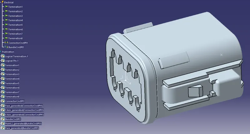
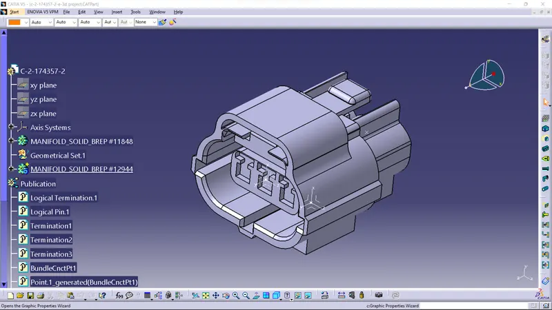
- NOW WE DEFINE THIS PART AS AN ELECTRICAL ELEMENT/CONNECTOR, WITH THE NUMBER OF TERMINALS.
- CONNECTOR CONNECTION AND BUNDLE CONNECTION IS DEFINED IN THE ELECTRICAL PART DESIGN WORKBENCH.
2) THE SAME PROCESS WAS FOLLOWED FOR THE SECOND CONNECTOR. HERE WE NEED TO INCLUDE THE CONNECTOR-CAVITY CONNECTION POINT. THIS IS DONE TO FIX THE CLIP ON TO THE CONNECTOR.
THE CLIP HAS TO BE DEFINED AS A CAVITY IN THE ELECTRICAL PART DESIGN WORKBENCH.