Wiring harness design in CATIA V5 - 3D modeling Week 2 Challenge
WIRING HARNESS DESIGN IN CATIA V5 – 3D MODELLING
AIM:
To Download following connectors & Connector clip cad data from given link & define it as Electrical Connector using Electrical Part design Workbench. Define all the necessary properties to Connectors & Clip.
Typical design flow of EDS System.
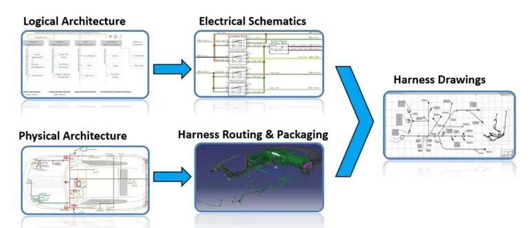
Defining the connector
We need to define the connector by following the below steps.
- Download the connector data.
- Create required geometrical parameter.
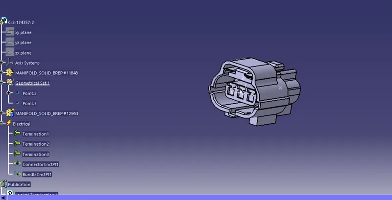
- Define part as electrical connector.
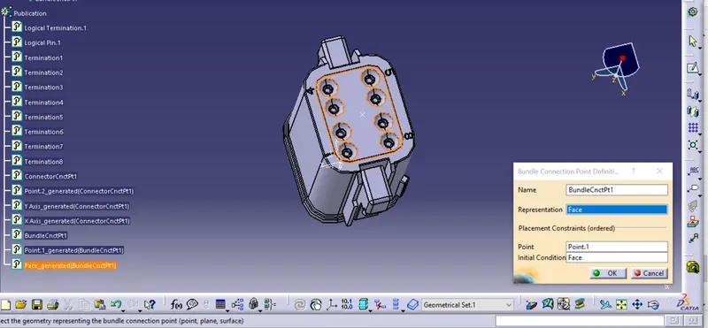
- Define bundle connection point.
- Define connector connection point.
- Define cavity connection point.
Defining the mounting clip
- Download the clip 3d data.
- Create the geometry parameter.
- Define the part as mounting component.
- Define the part as cavity.
Defining the connector is described below
- Downloaded the cad data from the supplier's website.
Then we have to put the axis system on the created points of the connectors with same orientation to ensure the correct assembly of the components.
- Defining the part as connector using the define connector command by selecting the command and selecting the component.
- Define the connector connection point and select the required geometry inputs for connector connection.
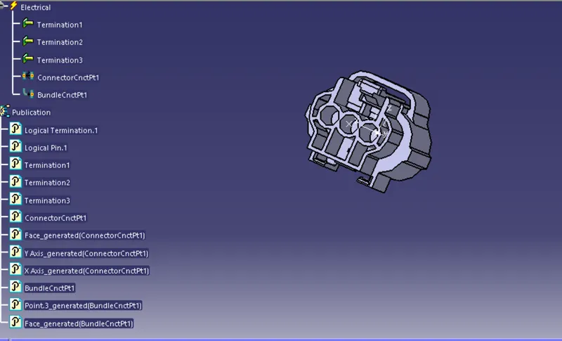
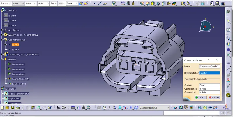
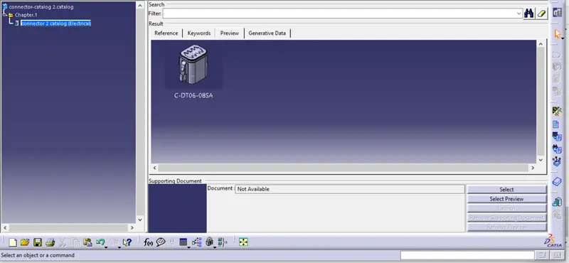
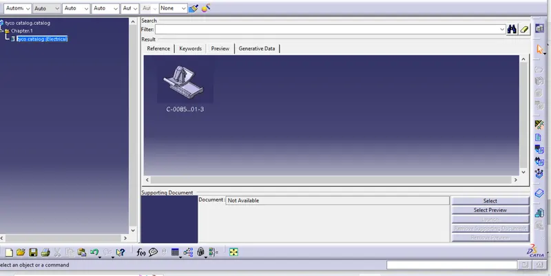
From the CATIA Start menu, select Infrastructure > Catalog Editor to open the Catalog Editor workbench . Create a catalog from scratch using one of both methods available: Using the Catalog Editor interactive commands: Activate the chapter under which you want to create a chapter or a subchapter.
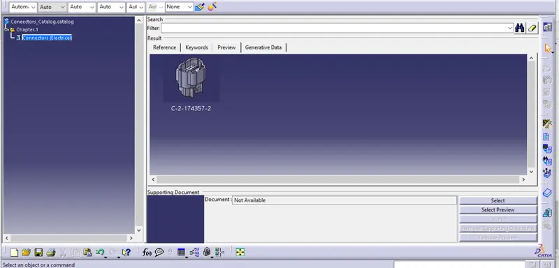
After defining the connectors we need to define the clip also, defining the clip also has various step in it.
- For clip we need to define it as mounting component, and select the required input needed for defining it as a mounting component.
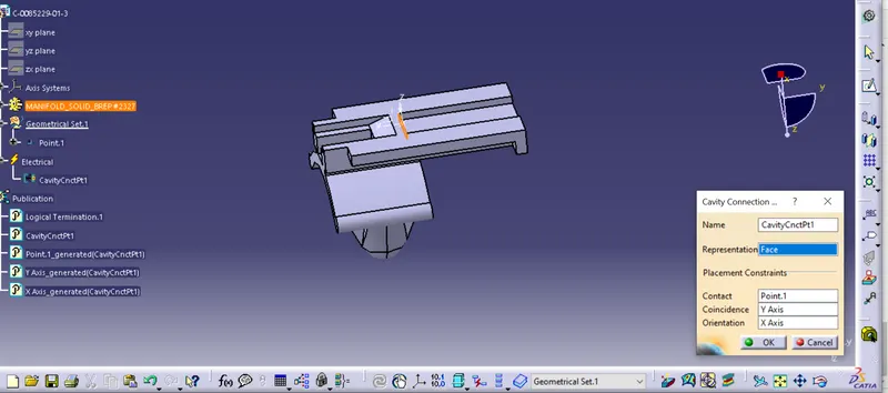
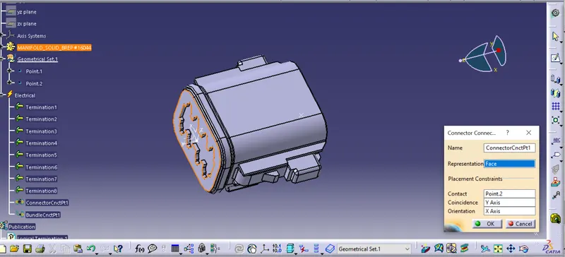
- Define bundle connection point and selecting the required input from the created geometries such as axis and points and face.