Week 9 Tension and Torsion test challenge
Tension and Torsion test of a specimen:
AIM:
To study and perform explicit dynamic analysis for tension and torsion test of a specimen. There will be two different analyses on the same specimen with different type of displacement and get results for Equivalent stress, Equivalent elastic strain and the total deformation in the model and grid dependency test was also performed to optimize the element size for better accuracy.
Case 1: Tensile test to be performed on specimen.
Case 2: Torsion test to be performed on specimen.
DYNAMIC ANALYSIS SETUP FOR SPECIMEN:
I. GEOMETRY:
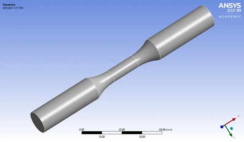
The CAD model of explicit analysis specimen is imported in Ansys dynamic structural environment. Then, the model is generated and checked if any abnormalities are present in the model. Generally, we have to perform two individual tests and according to that we have to analyze the results.
Case 1: Tensile test to be performed on specimen.
In this test, we have keep one end fixed, and other end will be displayed in linear direction. It is based on the principle of material science and engineering in which a sample is subjected to a controlled tension until failure. Properties that are directly measured via tensile test are ultimate strength, breaking strength, maximum elongation and reduction in area.
Case 2: Torsion test to be performed on specimen.
In this test, we have keep one end fixed, and other end will be displayed in angular direction. It is based on principle that it twists a specimen to a specified degree, with a specified forces or until the material goes under fracture effect. It evaluates the properties of materials or devices while under stress from angular displacement.
II. MATERIALS:
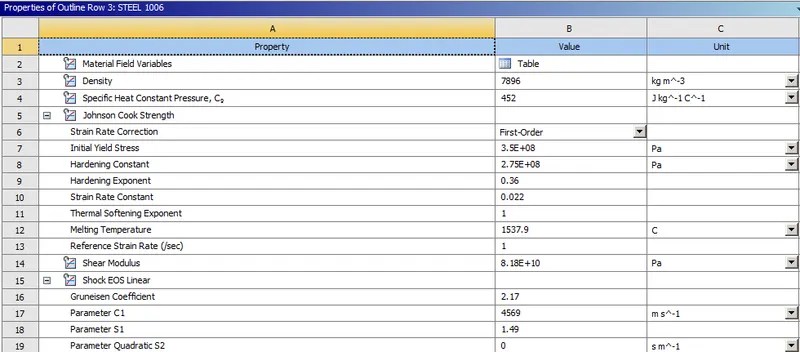
Below are the materials which is used to perform analysis for the dynamic analysis of specimen. The analysis is carried out for each material individually.
Specimen: Steel 1006
The details of each material has been carried out below as shown in the image:
III. COORDINATE SYSTEM:
Case 1: Tensile Test
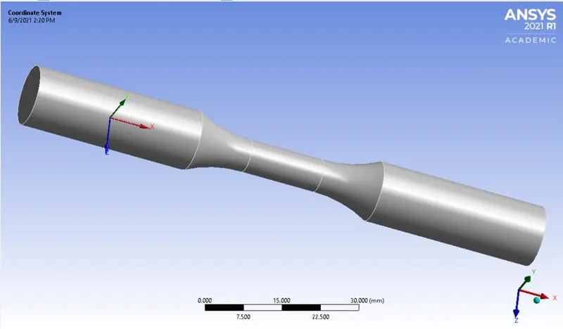
A. Coordinate system:
- As, like global coordinate system we have to generate the local coordinate system on the shoulder area which are used for sphere of influence in face sizing of different portions in tension test.
- Likewise, we have to select one face of grip section as its geometry selection part.
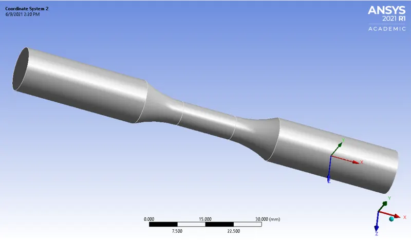
B. Coordinate system 2:
- As, like global coordinate system we have to generate the local coordinate system on the shoulder area which are used for sphere of influence in face sizing of different portions in tension test.
- Likewise, we have to select another face of grip section as its geometry selection part.
Case 2: Torsion Test
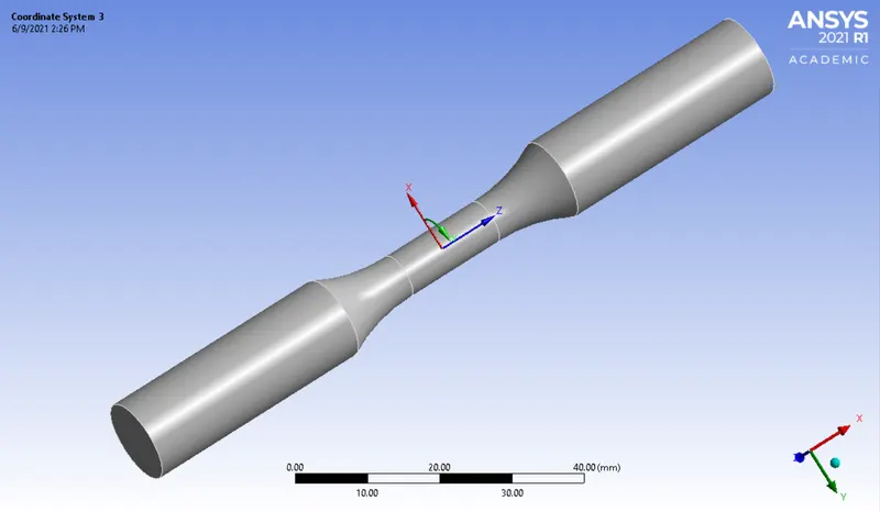
Coordinate system 3:
- As, like global coordinate system we have to generate the local coordinate system on the shoulder area which are used for sphere of influence in face sizing of different portions in torsion test.
- Likewise, we have to select another face of neck section as its geometry selection part.
IV. MESH:
Basically, we have preferred default mesh for whole setup.
Case 1: Tensile Test
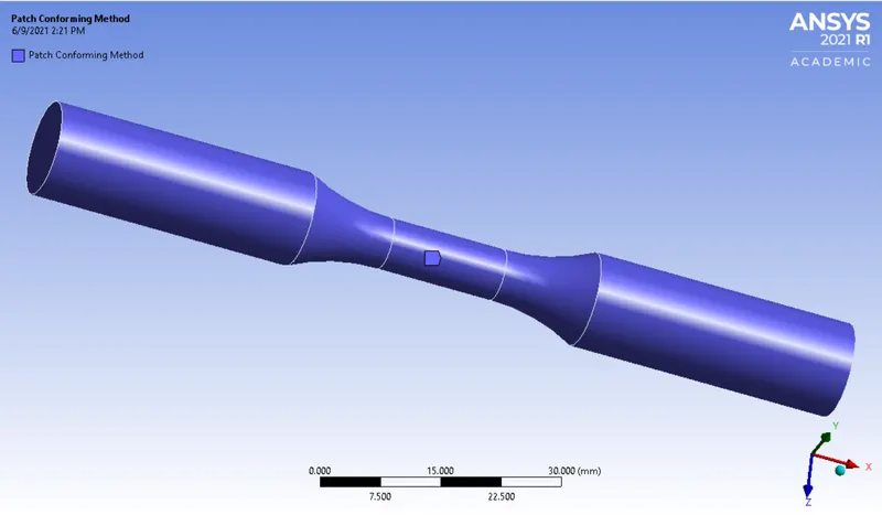
- As, we have to used Patch conforming method and used tetrahedron meshing for the specimen body.
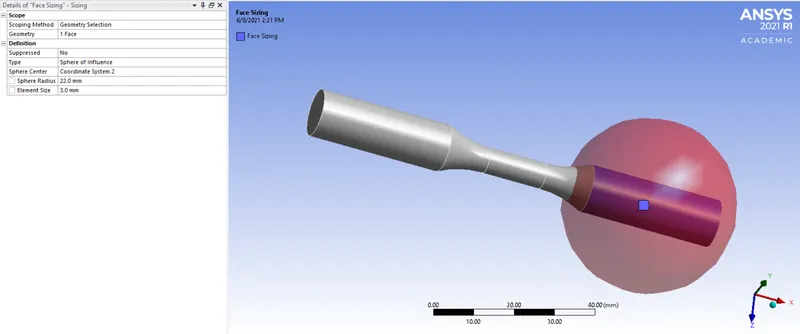
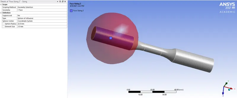
- Also, for the sizing of both grip section, we have used face sizing and sizing is applied with help of 'Sphere of influence', with radius and element size of '22mm' and '3mm.'
Case 2: Torsion Test
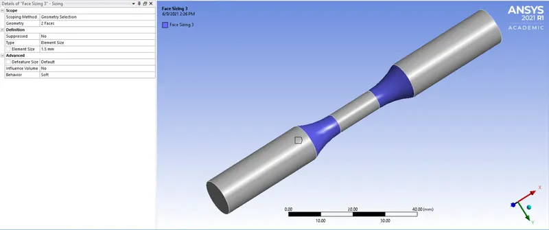
- For torsion test, in addition to above mesh criteria, we have used face sizing for the shoulder areas.
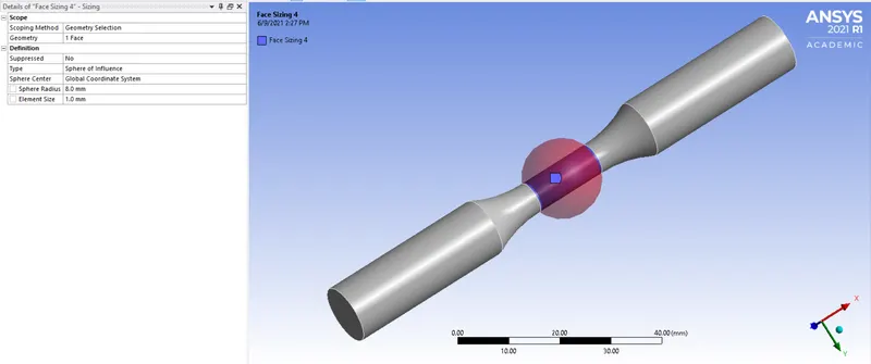
- Likewise, face sizing is also done for shoulder and neck portion with the help of element size of 1.5 mm for shoulders and 'Sphere of influence', with radius and element size of '8mm' and '1mm.'
V. ANALYSIS SETTINGS AND BOUNDARY CONDITIONS:
A. ANALYSIS SETTINGS:
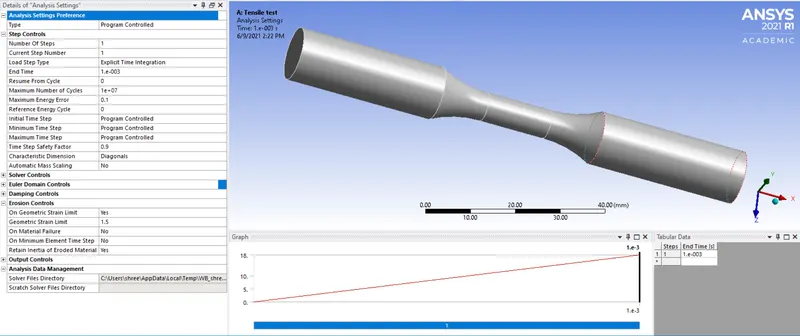
For this analysis the number of steps is set to 1 with maximum number of cycles is 1e+07 and end time is 1e-3 and it is defined by time, hence initial, maximum and minimum time will be program controlled.
B. BOUNDARY CONDITIONS:
1. Fixed Support:
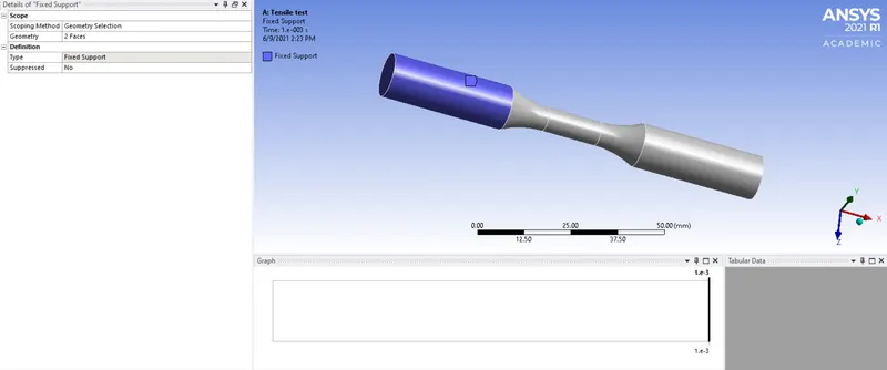
Basically, we have to fix the part so to analyze the results. Therefore, we have fixed the 2 faces of grip section as its geometric selection and we have selected it as fixed type support.
2. Displacement:
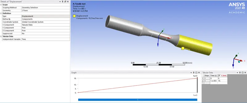
Case 1: Tensile test:
As, we have to select the 2 faces of grip section as its geometric selection part. Then its type is specified by displacement and its coordinate system is defined by 'Global coordinate system'. Then, its Y and Z component gets value as constant and X component value gets linear direction displacement in tabular form.
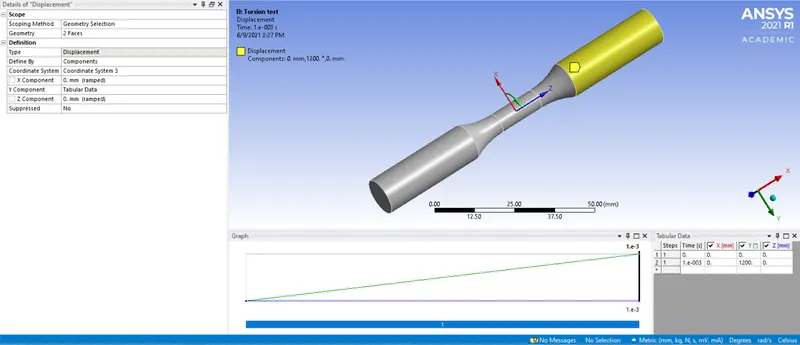
Case 2: Torsion test:
As, we have to select the 2 faces of grip section as its geometric selection part. Then its type is specified by displacement and its coordinate system is defined by 'Coordinate system 3'. Then, its X and Z component gets value as constant and Y component value gets angular direction rotation in tabular form.
VI. POST-PROCESSING RESULTS:
Now, we have to compare the strain, deformation and stress on the basis of different materials. Then, we have to analyze the result for total deformation, equivalent stress and strain for dynamic analysis for specimen. The results are as shown below:
Case 1: Tensile test to be performed on specimen.
I. Total deformation:
II. Equivalent stress:
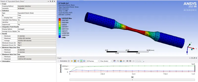
III. Equivalent strain:
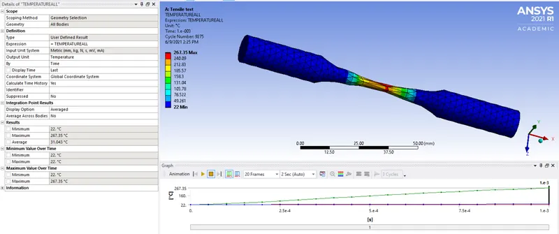
IV. Tempreature generated:
Case 2: Torsion test to be performed on specimen.
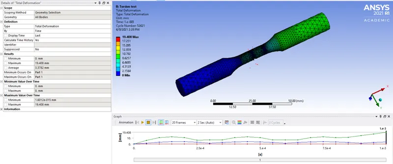
I. Total deformation:
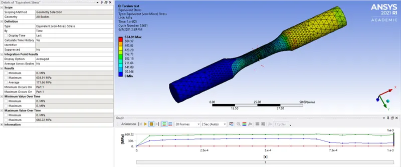
II. Equivalent stress:
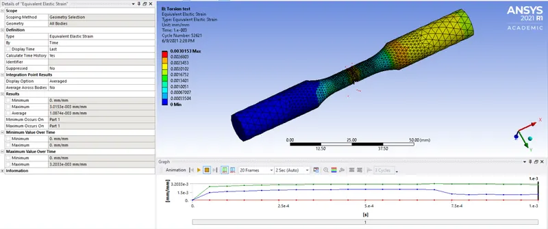
III. Equivalent strain:
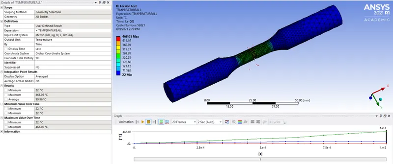
IV. Tempreature generated:
VII. POST-PROCESSING RESULTS:
|
Parameters |
Tensile test |
Torsion test |
|
Maximum Total Deformation |
18.004 mm |
19.408 mm |
|
Minimum Total Deformation |
0 |
0 |
|
Maximum Equivalent elastic strain |
3.045e-003 mm/mm |
3.0153e-003 mm/mm |
|
Minimum Equivalent elastic strain |
0 |
0 |
|
Maximum Equivalent stress |
631.28 MPa |
634.91 MPa |
|
Minimum Equivalent stress |
0 |
0 |
|
Maximum Temperature generated |
267.35 °C |
468.05 °C |
|
Minimum Temperature generated |
22. °C |
22. °C |
Equivalent stress:
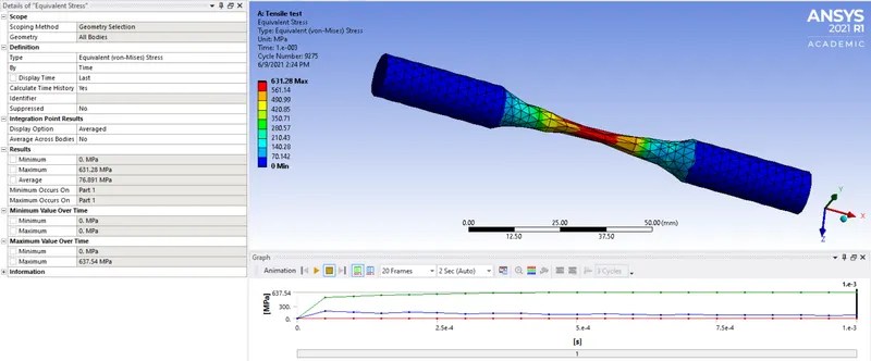
Case 1: Tensile test
- From contours, plots and data, we can observe that maximum stress on the specimen is 631.28 MPa.
- We can see that at 5e-4 s, necking happens, and then the value of stress is slightly decreasing.
- After necking, specimen will not withstand more stress, so the stress is decreasing after necking.
- We can observe stress in lateral direction, which quite low compared to axial stress.
Case 2: Torsion test
- From contours, plots and data, we can observe that maximum stress on the specimen is 634.91 MPa.
- We can see that there is a fracture near 7.5e-4 s.
- We can observe that to reach up to maximum equivalent stress, specimen is taking more time in torsion than tension.
Total deformation:
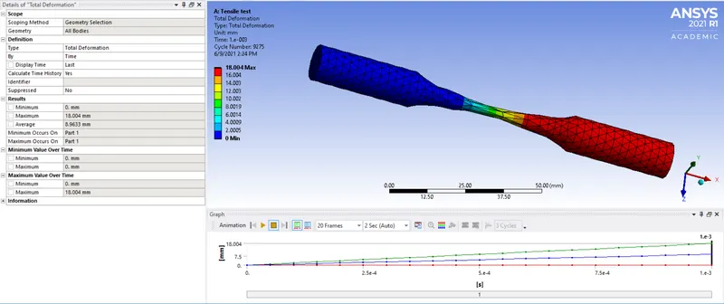
Case 1: Tensile test
- From deformation results, we can see the maximum deformation is 18 mm.
- As, we know that we have streched the specimen only up to 18 mm, so we are getting maximum 18 mm deformation.
- Also the displacement is given in X-direction, so we are getting linear graph of deformation.
- Also, we can see the deformation in Y-direction also due to lateral strain.
Case 2: Torsion test
- Here, we can see the maximum deformation is 19.408 mm
- So, for the higher angle of rotation, very small deformation is happening.
- Also we can see that particles are exploding due to fracture.
- We can see the ups and downs in graph, which is due to rotation of the one end of specimen.
Equivalent strain:
Case 1: Tensile test
- From strain results, we can see that strain is very low compare to stress.
- At the necking point, there is only 0.3% strain.
- After necking, there is no significant change in strain, it remains nearly constant.
- Lateral strain can be observed from the graph.
Case 2: Torsion test
- From strain results, we can see that strain is very low compare to stress.
- At the fracture point, there is only 0.3% strain.
- After fracture, there is a little decrease in strain, and becomes nearly constant.
Tempreature generated:
Case 1: Tensile test
- From the tempreature results, we can observe the significant change in tempreature.
- As the deformation increases, stress also gets increased, and there will be heat generation.
- So, with increases in stress, we can see the rise in tempreature.
- Here the tempreature of the specimen is rising upto very high 267.35 degree.
Case 2: Torsion test
- From the tempreature results, we can observe the high change in tempreature.
- As the deformation increases, stress also gets increased, and there will be heat generation.
- So, with increases in stress, we can see the rise in tempreature.
- Here the tempreature of the specimen is rising upto very high 468.05 degree.
- Excessive amount of heat is generating due to shearing effect at the neck area of specimen, where twisting is happening and the particles are getting exploded due to fracture.
CONCLUSION:
- From the above results, we can conclude that the failure of the specimen in tension test is due to permanent deformation due to elongation and sue to neck generation. This concludes that failure of the specimen is due to max. tensile stress.
- Failure of the specimen in the torsion test shows, the flat failure surface. This concludes that failure is due to maximum shear stress, also it is ductile material, which indicates the failure in the plane of maximum shear stress perpendicular to the axis of the specimen.
- Also, we can see that tempreature in torsion test is very high due to high shear stress.
- In tension test, lateral stress also occurs due to axial tension and reduction of the cross section area at neck portion.
- In torsion test, shear stress is important due to twisting of the specimen in the angular direction.
- As the material is steel 1006, we know from the results that, the fracture in tension test initiates in the necked portion.
- For the torsion test fracture is occuring in flat surface, or in shear plane, so steel is failing at large shear strains.
- Here the tempreature is also important factor in both the tests, as we know that at higher tempreature elongation or fracture of the material can differ.