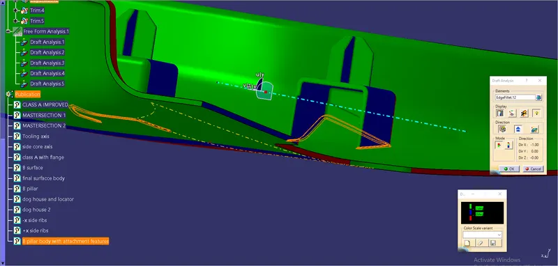
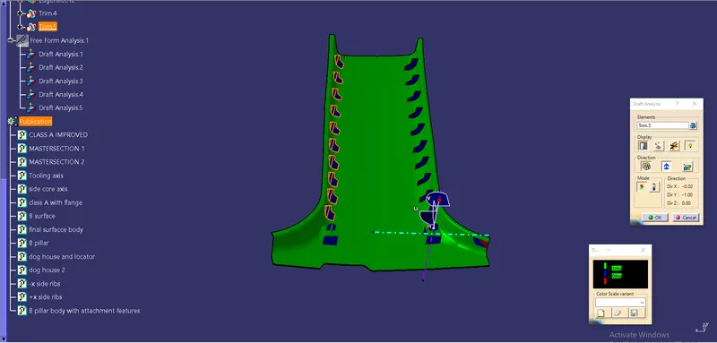
Week 9 - Project - Master Section Development
Aim:
To create B pillar using the given Master section with class A surface.
The CAT part file for the B pillar is downloaded and opened in Catia. And the A surface is then checked for any open and a boundary is created.
Creating tooling axis:
The tooling axis is created by taking the dog house locator intersection in the master section is taken as the reference. And the edge of the locator is exracted, and created axis lines by using the bisecting line command.
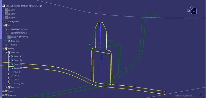
Draft analysis on A surface:
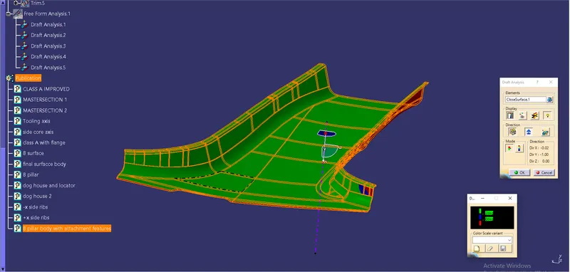
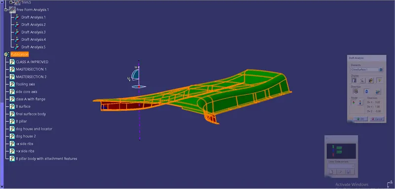
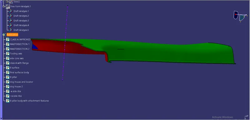
After creating the tooling axis. The A surface is then held for draft analysis by locking the draft direction along the tooling axis. A small part in it fails but as it is a minimal value it can be considered.
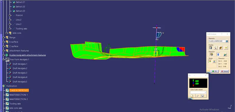
Creating flange in the A surface:
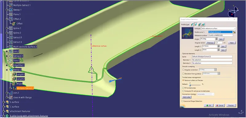
The line of the flange in A surface is extracted from the master section. Then the tip from the A surface where the flange will be is also extracted by the boundary option using no propogation option. Then the adjacent faces which is in contact with the extracted boundary line is also multiple extracted. As the boundary has many patch points the boundary line is smooth curved. With these inuts the flange for the A surface is created, and cross checked with the flange angle in the master section until they become parallel, and the length is given as per the master section.
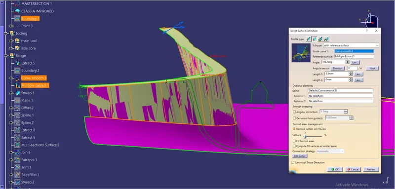
After sweeping the flange it is then offsetted, as the flange for the A surface comes down as per the master section.
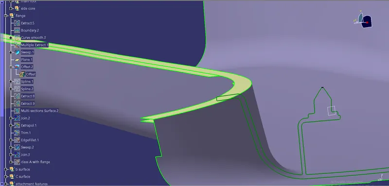
As the smooth curve is so curvy a small section failed to connect. To create the missed surface multi section command is used. Then it is joined as one. After joining, it is trimmed with the A surface.
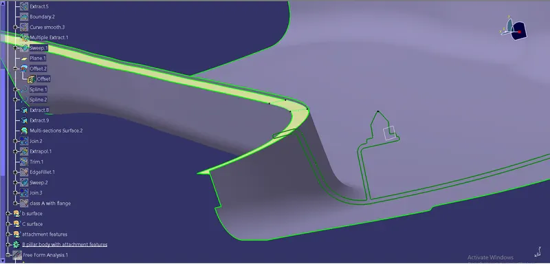
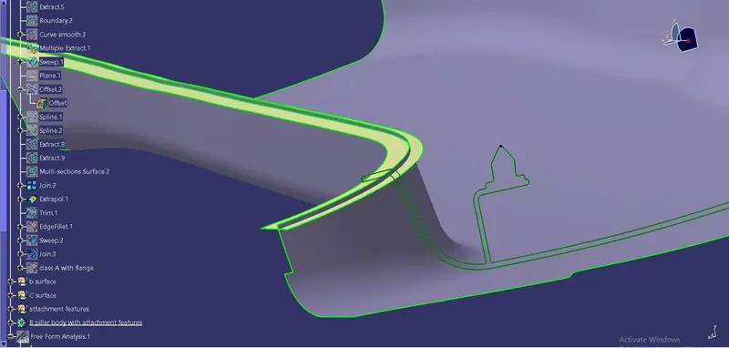
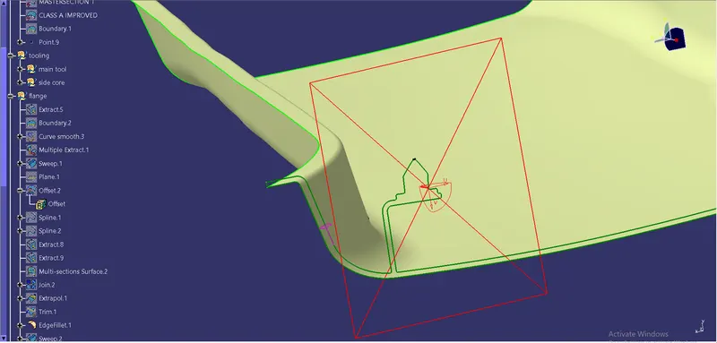
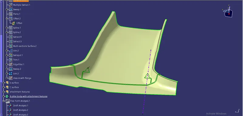
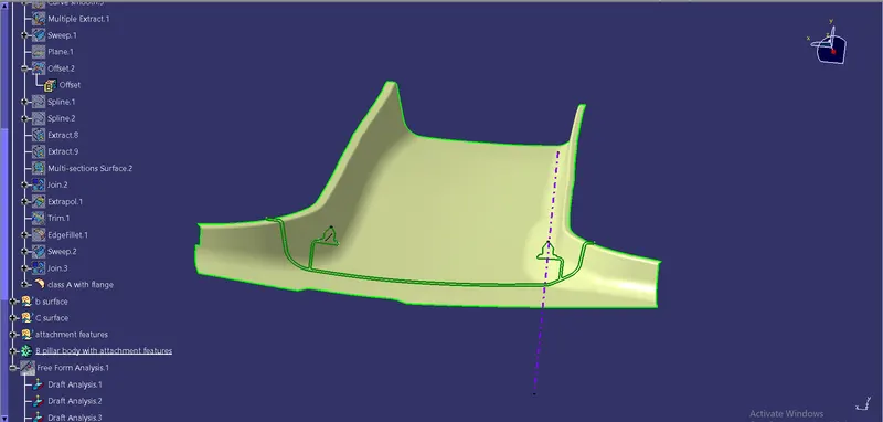
This same procedure is used to create the other flange on the other side.
Creating B surface:
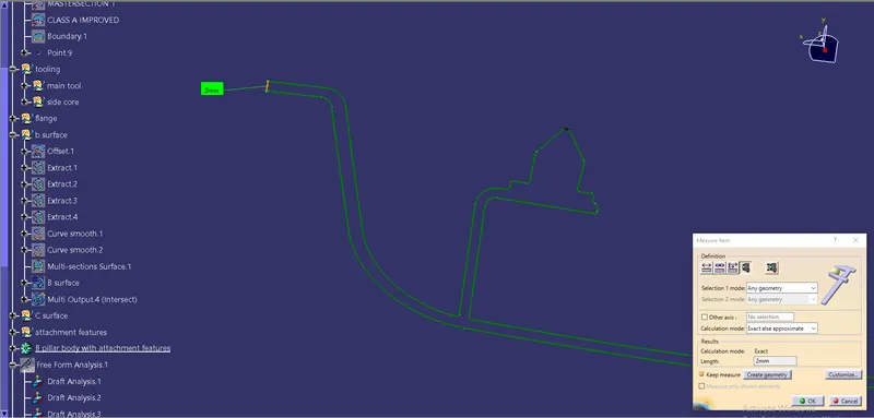
The B surface is created by offsetting the A surface. So the thickness of the B pillar is checked in by mesuring the gap distance in the master secteion. Then A surface is offsetted to the messured value (i.e., 2mm).
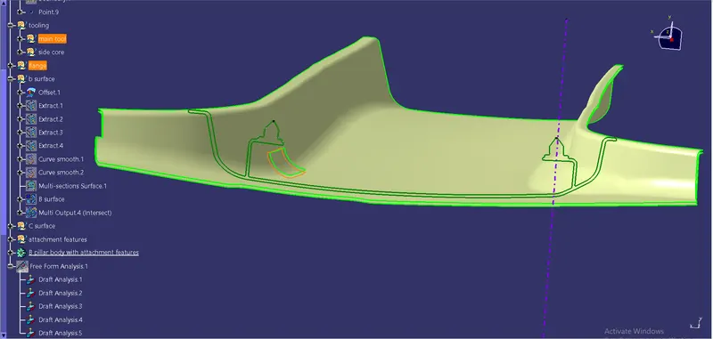
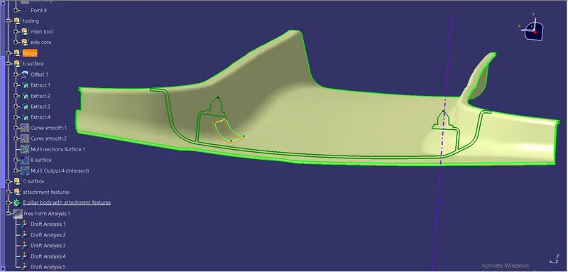
As the error occurs, a part on the surface was not offsetted. So to over come it and to clear it. A multi section is created by extracting all the 4 open boundaries induvidually. Then they are joined as one, and the B surface is created.
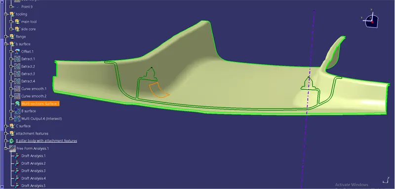
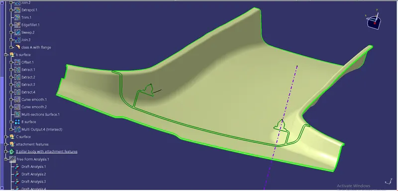
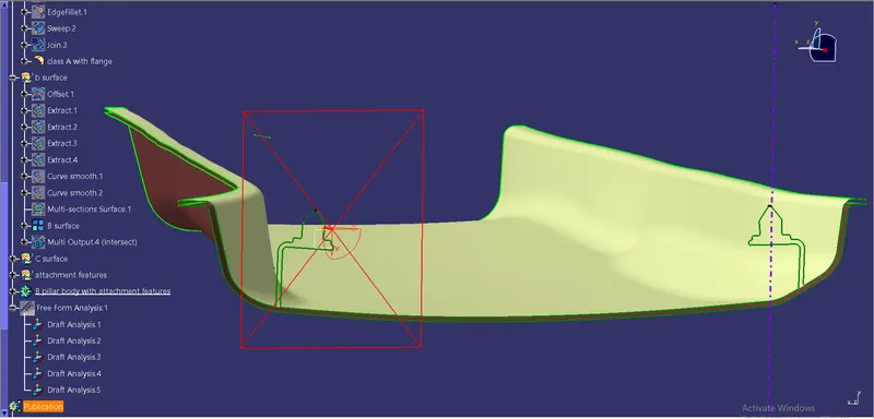
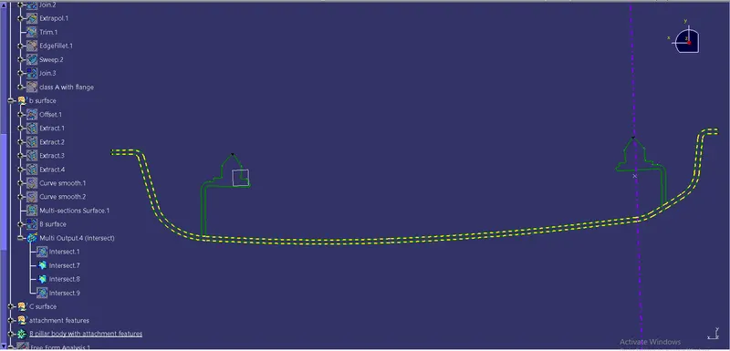
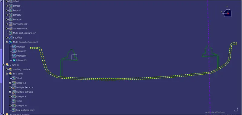
The intersect of the A surface and the B surface (dotted yellow lines) is checked with the master section(green line).
Creating C surface:
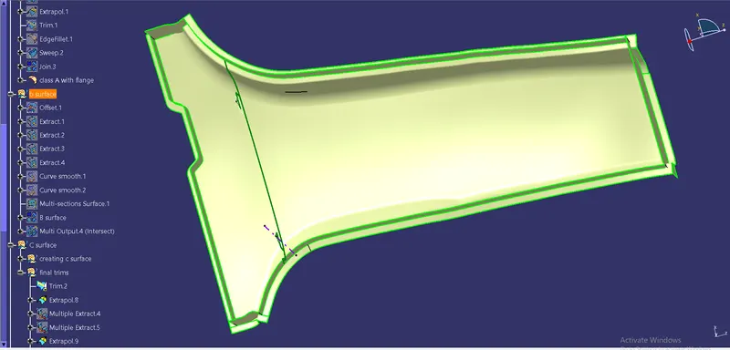
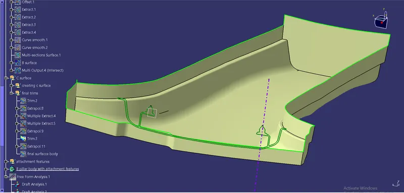
The boundary of the A surface with flange is extracted, to create the C surface. In the front a irregular shape occured so to correct that a line is drawn on the surface and it is splitted with the surface, as it caused error. And the edges are been extracted.
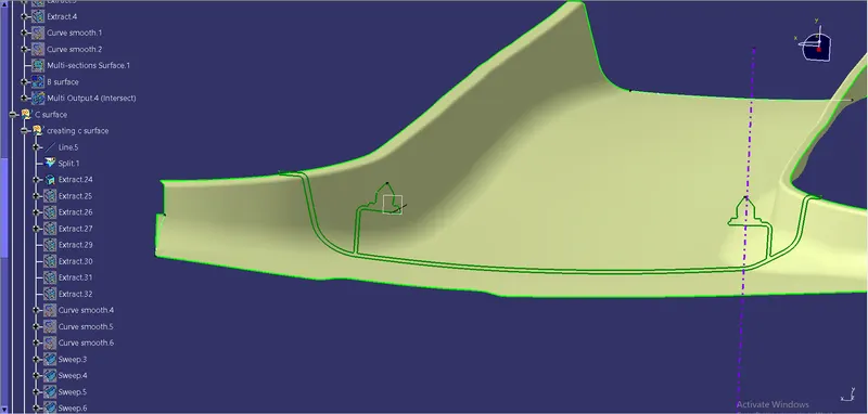
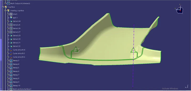
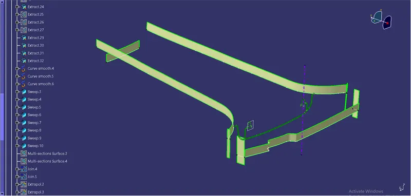
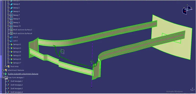
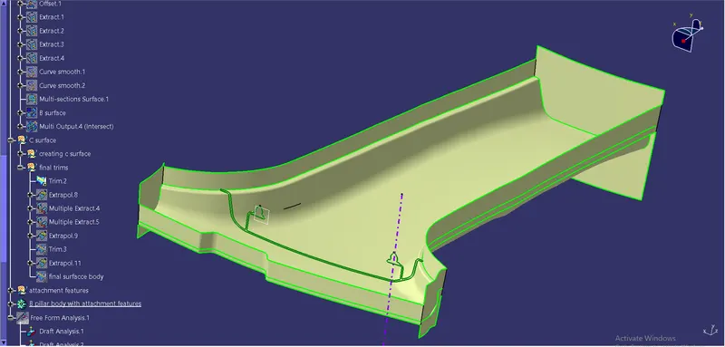
Then they are sweeped one by one. As usual error occurs, so the side in the front is been divided into three part and the alternate are extrcted and sweeped. Then multi section is used to create the fill the missed surface. Then they are joined as one surface part. Then all the sweep are trimmed together, after extrapolating the edges which ae required.
Creating closed surface:
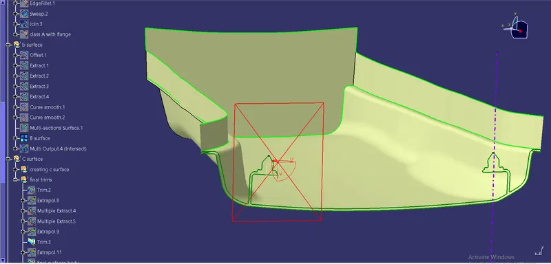
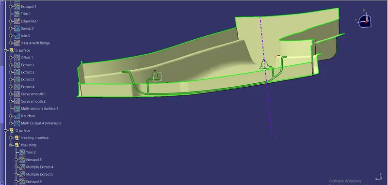
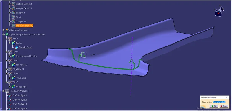
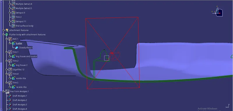
As they didnt intersect with each other at some place, the A surface is extrapolated. Then they are trimed together. This same is done with the B surface. It was also extrapolated and trimmed and the close surface is created. And it is filled with solid.

Creating the attachment features:
Dog house with 4 way locator:
To sketch the dog house a point is and a plane is created using the master section as a reference and then it was isolated.
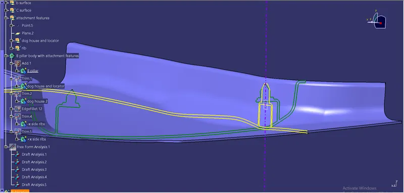
Then the sketch for the dog house is created and padded. To make it hollow, shell command is used.
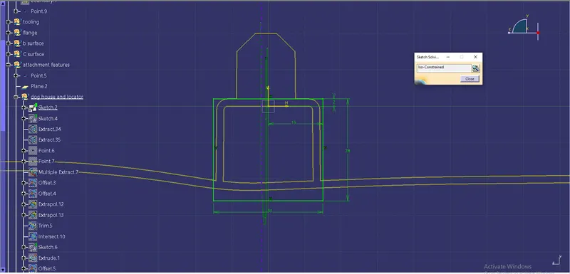
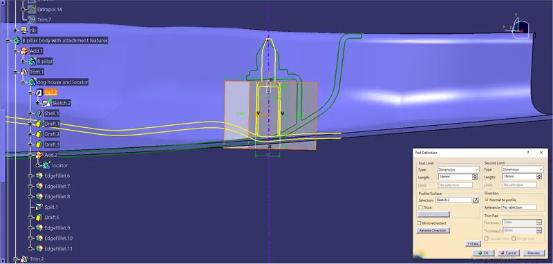
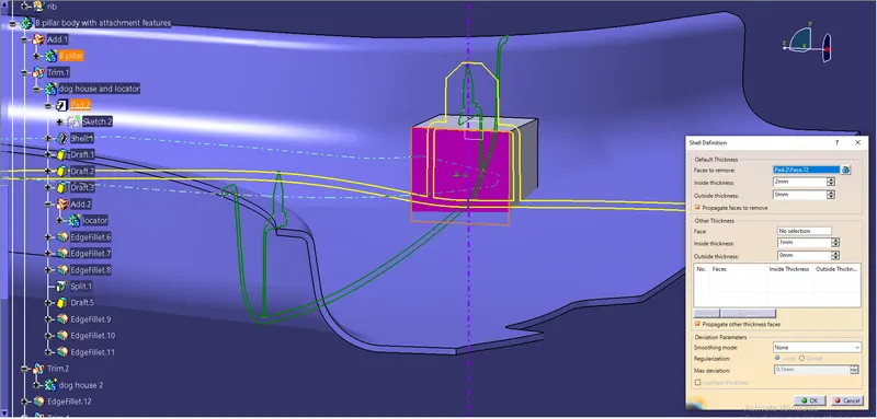
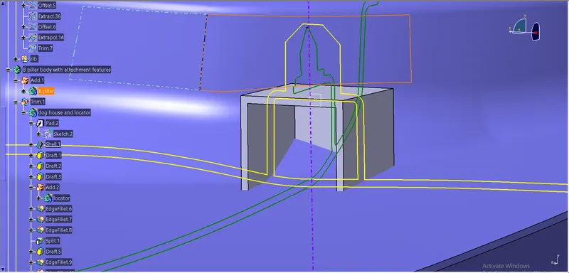
After making the dog house to the required shape, it is then drafted by giving the minimum draft angle on the outside and inside along the tooling axis.
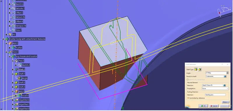
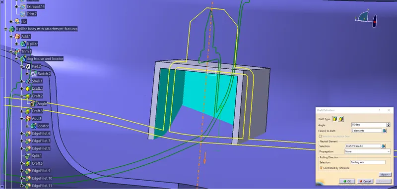
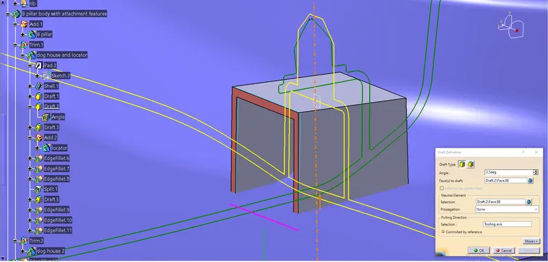
Then the sketch for the 4 way locator is drawn using the same point but in zx plane.
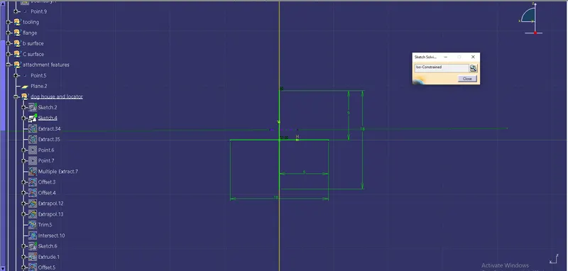
It is then padded and given chamfer to have a inclined edge for a easy movement for it to travel. Then the edges are filleted after giving draft angle. As the draft take the 2 filleted sides as one, so the fillet is given after drafting.
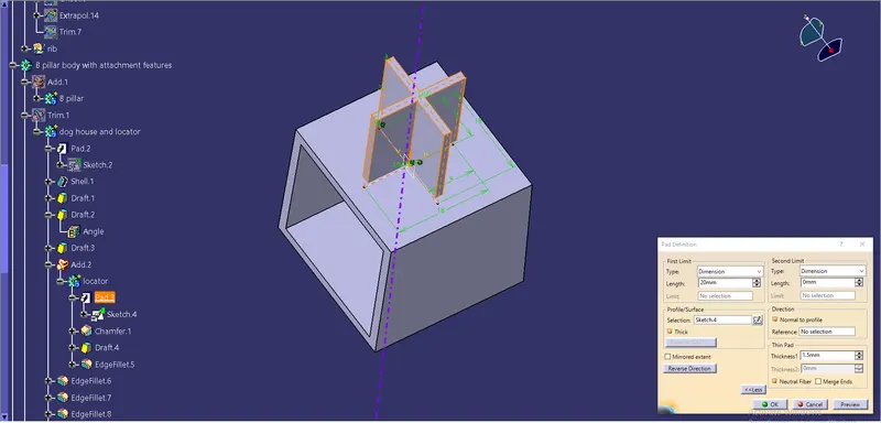
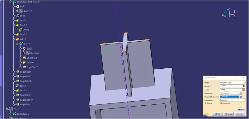
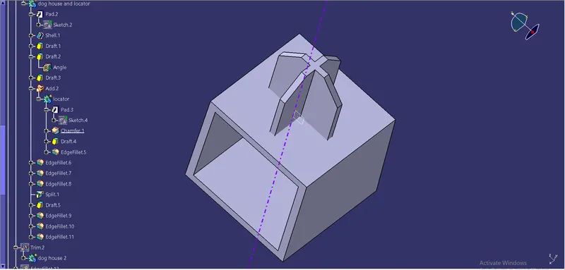
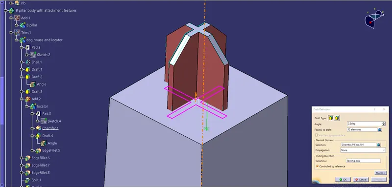
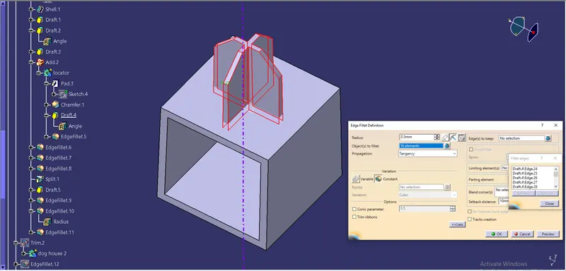
After giving all the fillets chamfer and draft the locator is added to the dog house. Cause the locator does not project inside the dog house it is added to it.
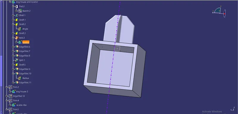
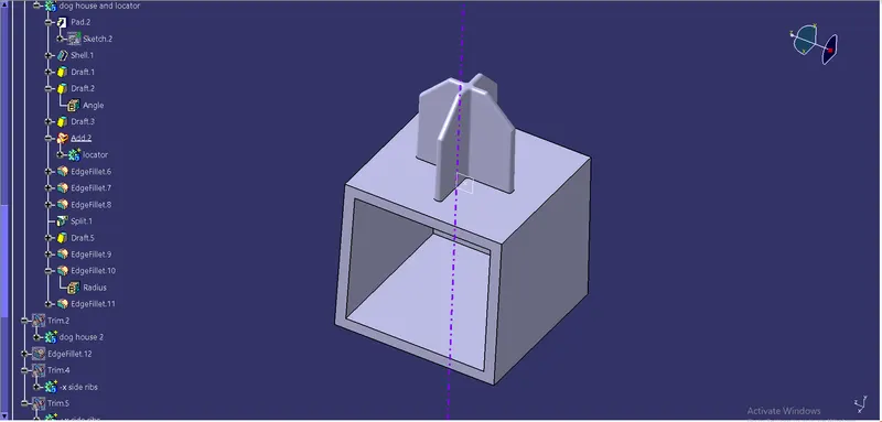
After adding the locator with the dig house, fillets are given to the edges of the dog house inside and outside.
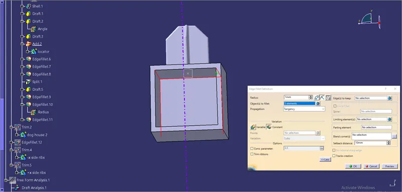
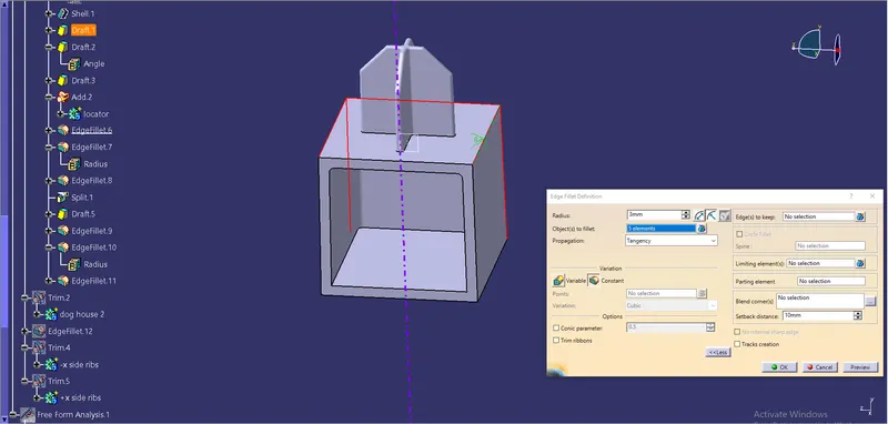
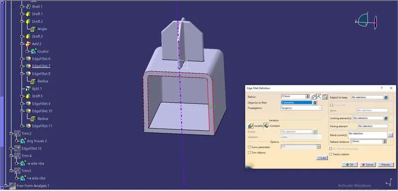
As per the design rule the thickness of the bottom of the dog house should be less than the real thickness. So the inner surface is extracted and offsetted to half of the original thickness of the dog house, as the offset cut goes outside dog house the offset value is reduced to 1 mm and is extrapolated.
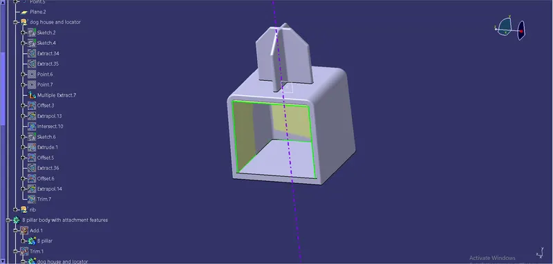
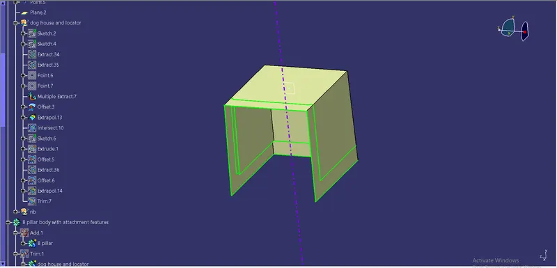
To create the base limit the B surface is offsetted too 5mm. Due to the edge curve in the B surface the dog house gets an undercut which cannot be made easily. So the B surface is intersected with the exrtrapolate made before. With the help of the interseted line a sketch is drawn in a way when extruded and cutted cuts the whole path and avoids the undercut. Which is then later extruded and performed split operation. But the extrude is open on both side, so to close one the back side. The back side in the inner side is extracted offsetted and extrapolated, so that it can be trimmed with the extrude and caan close one side.
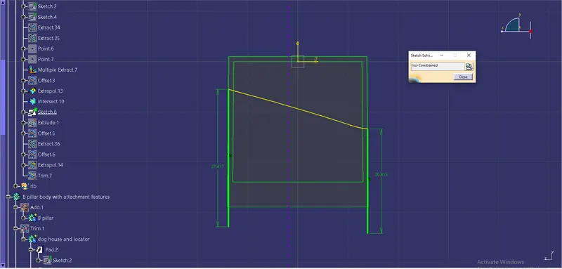
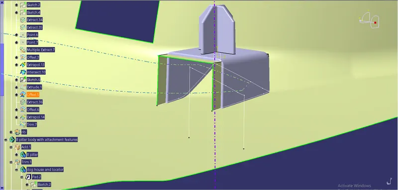
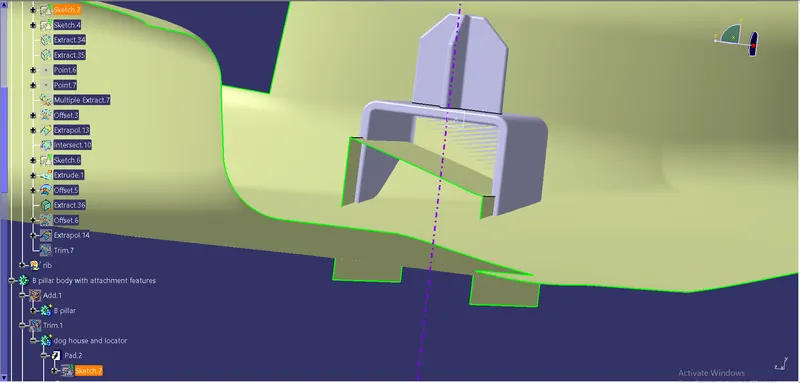
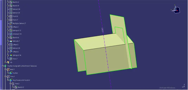
This is then spitted with the dog house to achive the design rule.
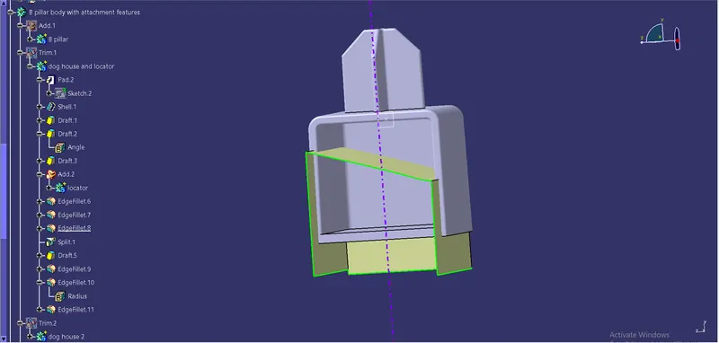
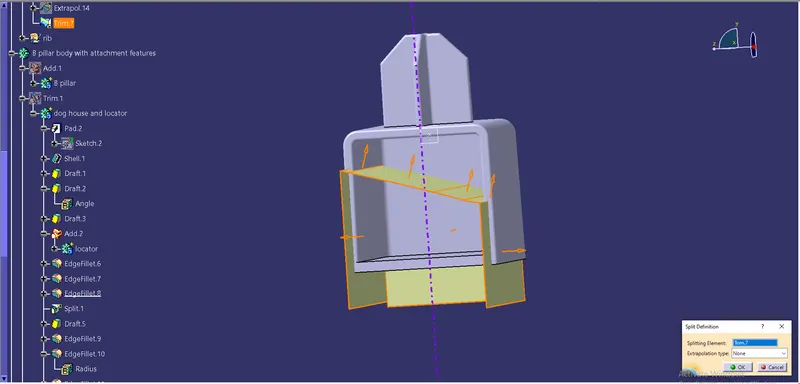
After cutting as per the design rules. A side core axis is created along the point created by extracting the dog house line from the master section. These cutted inner surface is then drafted along the side core axis, as it clears in side core.
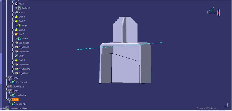
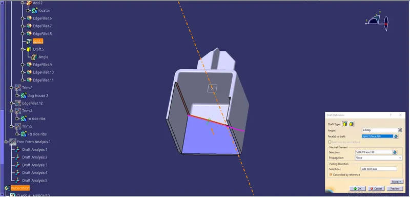
After creating the draft. The corner and edges formed after cutting are filleted.
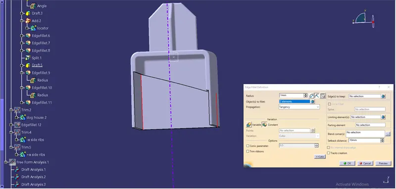
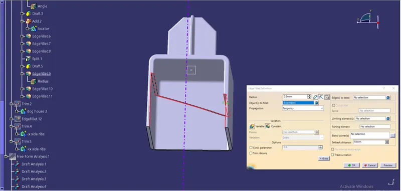
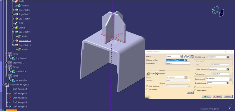
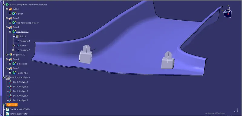
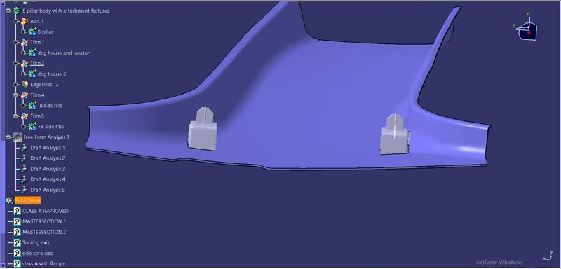
To create the 2nd dog house 2 extract is taken from the master section. And 2 points are created in the mid of the extract.
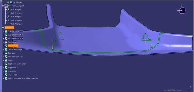
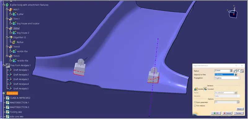
Then this created dog house id copied and pasted with link. And it is then translated from point to point. Then rotated to form and position it correctly. Then they are union trimed with the B pillar solid and filleted in the bottom joint.
Ribs creation:
The sketch for creating the rib is drawn and extruded.
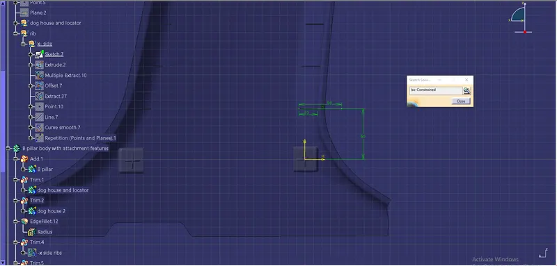
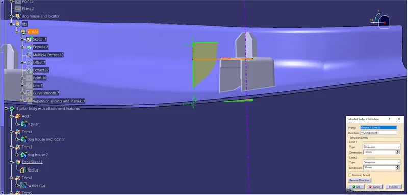
It is then thicknend to .8 mm as per the design rule.
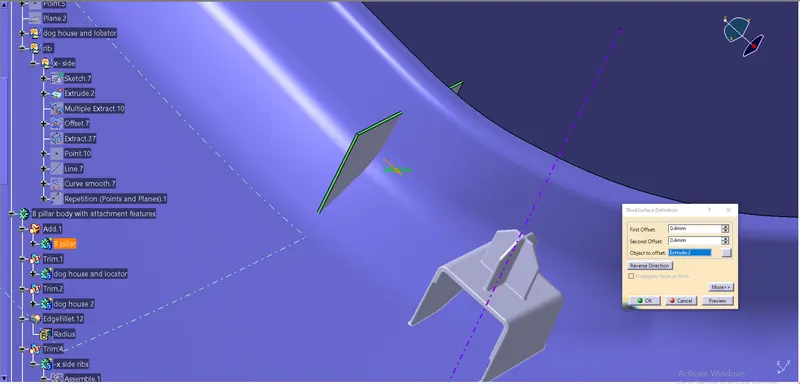
Then the adjacent surface is extracted and offsetted to split the rib to give its height as per mentioned in the rule. After spliting it is then drafted along the main tooling axis.
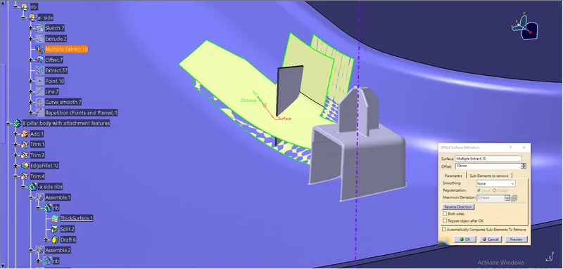
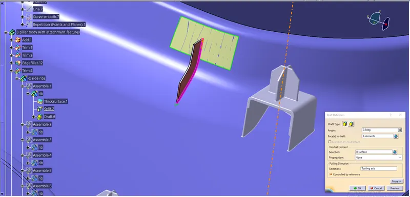
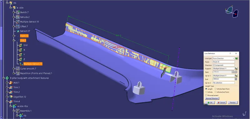
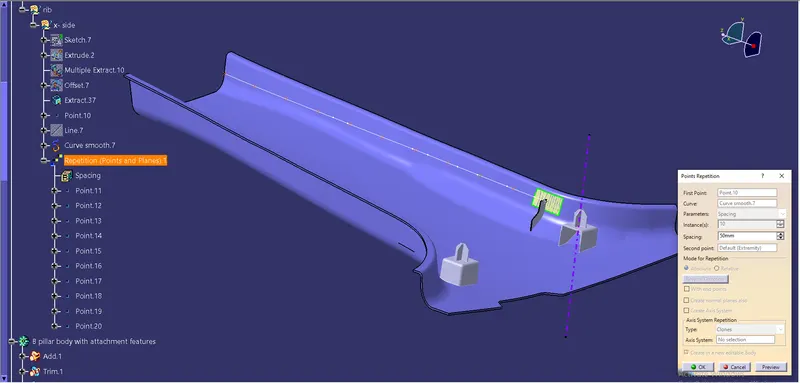
A line is created on the surface where the rib should be placed. Then point repetation is used to create points after every 50mm apart. So that the ribs can be placed on it. Then they are union trimed with the main body.
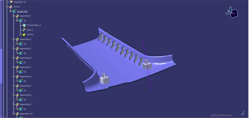
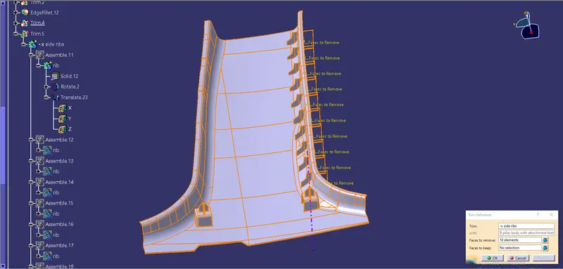
The same rib is copied and pasted after rotating and transalting the first rib to the opposite side. Then the remaining ribs are copied and pasted and moved through translating them with coordinates. And union trimmed with the main body.
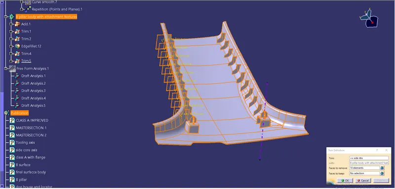
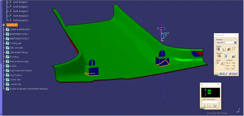
Draft analysis for all parts: