Week 9 - Project - Master Section Development
Tooling axis :
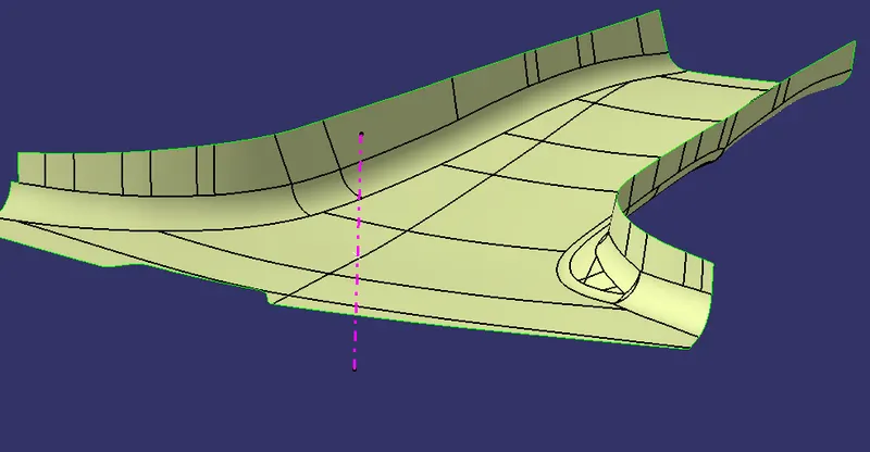
Tooling axis is created normal to the given class A surface of B pillar part. Tooling axis determines the movement of core and cavity in mould.
Improvising :
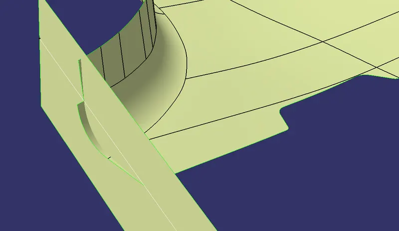
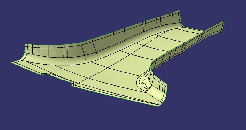
Class A surface has Some discontinuity which will be hard during production phase. So some improvements to the class A surface is done. Then the improvised class A surface is extrapolated to form a New Class A surface for the B Pillar part.
Flange for class A surface :
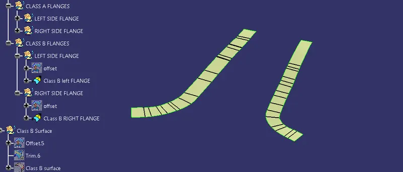
B pillars will have flanges for fixing purpose. So we have to create flanges for the B pillar. Boundary from the master section is extracted and curve smoothed. This curve smooth is swept perpendicular to the side face of the B pillar Class A surface. Also, the cthe created flange will be at some height and angle. The angle is then corrected and offsetted to the required height.
Flange :
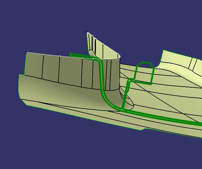
Flanges are created on both the sides of the class A surface.
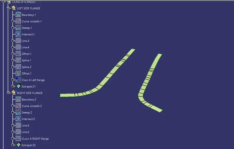
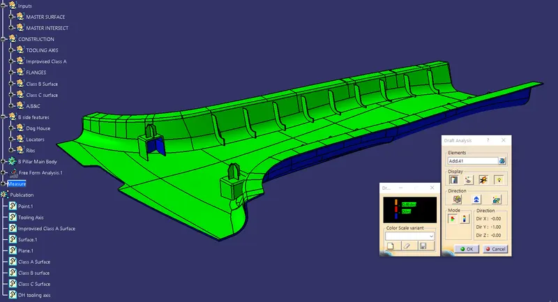
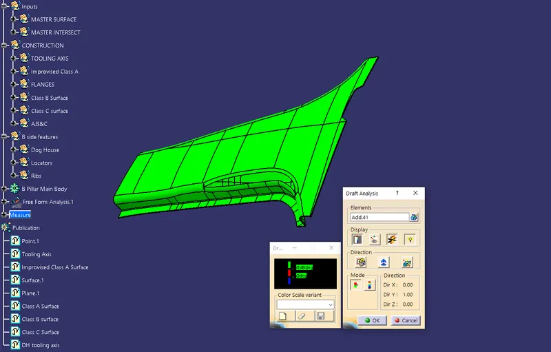
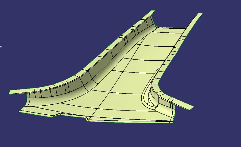
Joining the improvised class A surface with the impprovised flanges. To form new class A surface. This surface will be used for the class B production. After Adding flanges to the surface draft analysis is done.
Class B Surface :
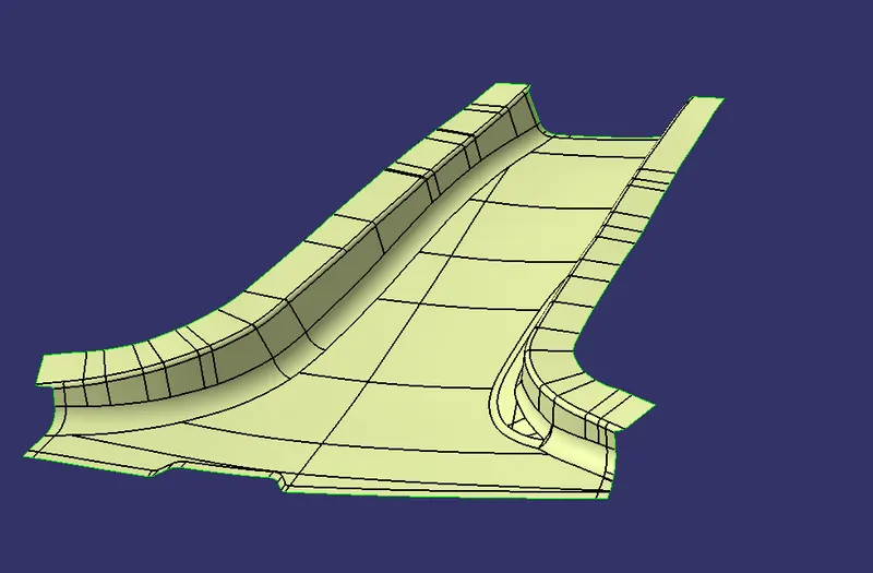
The improvised class A surface with flanges is offseted to 2.5mm to create Class B surface.
Class C Surface :
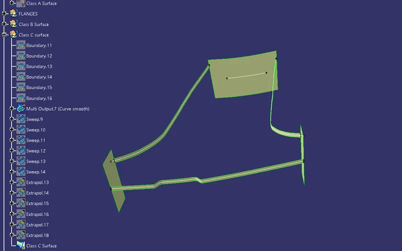
The boundaries of the improvised class surface with flanges is extracted and curve smoothened. This is then swept perpendicular to the class A surface to form class C surface. C surfaces can be created either with angular sweep with respect to tooling axis or surface based on the design.
Adding :
The class C surface is either joined or added with the class A surface. Here class A surface is trimmed with the class C surface to form the join of class A & class C surfaces.
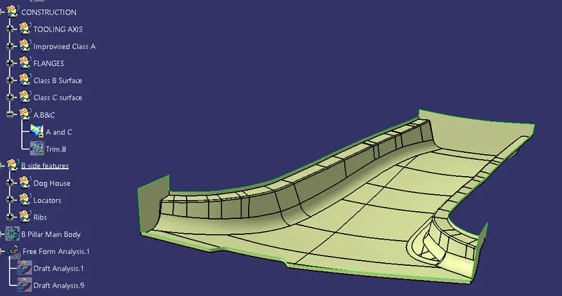
Final Part :
Now the class C surfaceis trimmed with the class A & C surface trin to form the final surface design for the part.
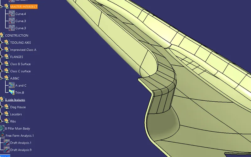
B - side features :
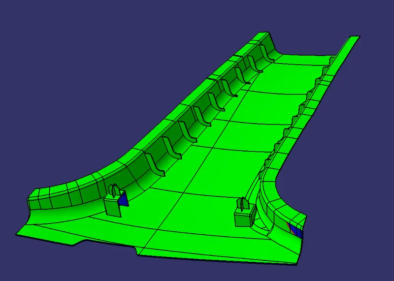
B side features are also known as attachment features. B side feature can be a flange or a heat stake or a locator or a dog house with push pin and snapfit. Here we are creating a Dog house for the locator to lay. Scine locators can not be too high for the strength factor. \
Dog House :
Dog house is an engineering feature used in plastic trim design. Dog houses are used as supporting feature. Sometimes other engineering features like snaps, locators etc.
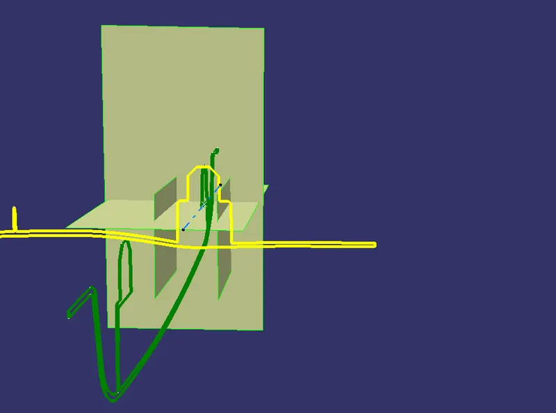
The master section for the dog house is opened and the profile is extracted from the master section. These extracts are then swept along with the slider axis as guide curve.
Slider axis :
Slider axis are created for the additional features and also for the production of cavity part in catia.
The extracted boundaries are swept and trimmed to form a base profile or class a surfcae for the dog house. This surface is then thickned to form a new solid part.
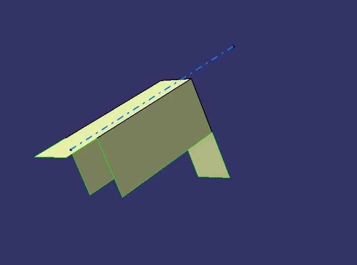
Coaring :
Coaring for the dog house is created to reduce the material loss and also reduce the formation of heat sinks on the Class A side of the solid body.
Desgin Guidelines for Dog house : ( from previous challenge )
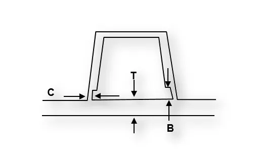
"C" is where the doghouse contacts the backside of the surface.
-
Doghouse wall thickness at the intersection of the part wall ( C ) should be 40% or less than the main wall stock ( T ).
-
Height of ( B ) should be between 3.0 – 6.0 mm
Locators :
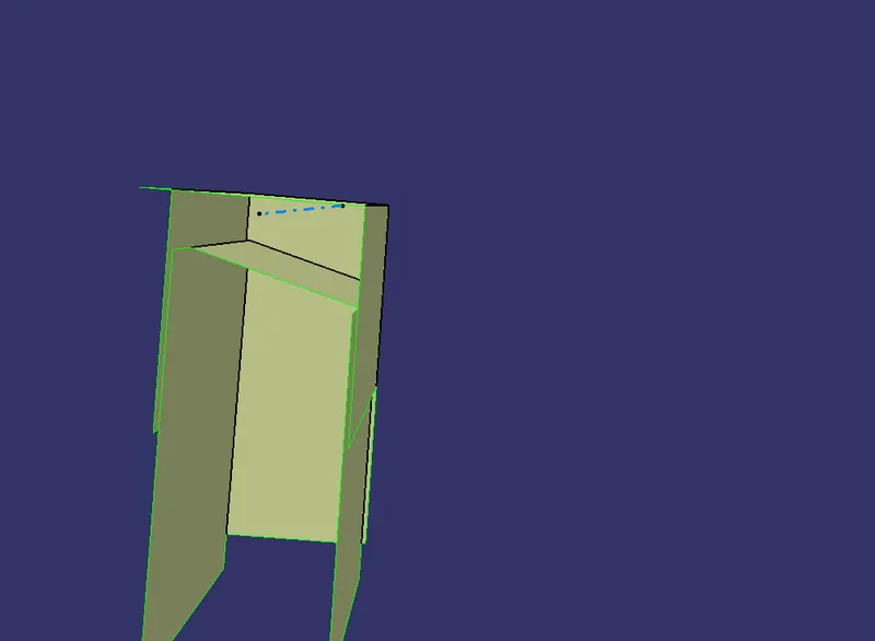
Loctaors are used to make the perfect fit for the plastic body to the fixing part. It will guide the part body to the ultimate positon parallet to the fixing part, also they will be helpful in placing the part in its desired position.
Ribs :
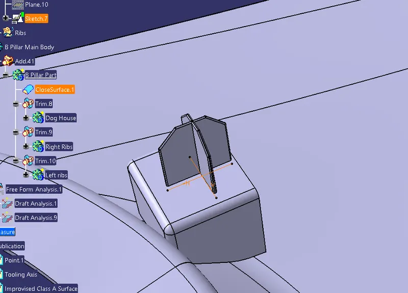
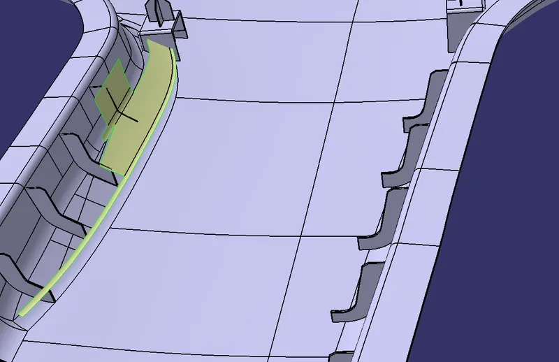
Ribs are strengthening elements to the part body. Ribs creation must obey certain design criteria like draft angle height and distance between the placement od ribs and also the position of ribs. Here ribs are created on the side wall. Where a line is drawn in the positioned sketch and is padded adn drafted to an angle of 0.5 deg.
for the distance placements of ribs , a cureve is extracted from the place where you feel the position of ribs will increase the strength. Then the curve is smothened and multiple points are created on the curve using the multi point command.
Spliting element :
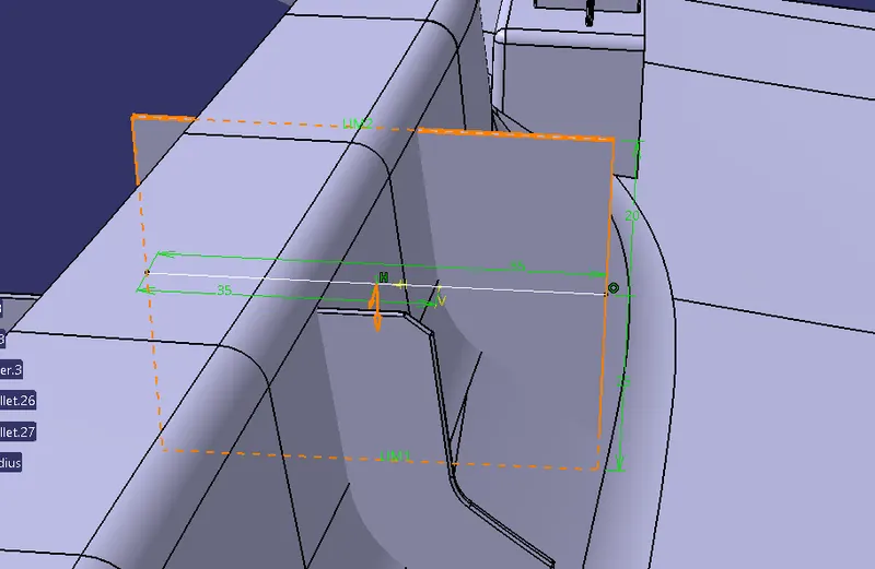
The side faces of the solid body is extracted and offseted to a maximum distance of 10mm in this part body. Then the offseted surface is splited with the rib. This will increates the design quality of the rib and also will reduce the materials.
Final part body :
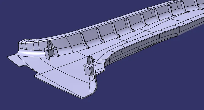
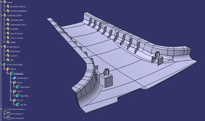
Now using the boleean operations all the seperate part body created are joined either using asssemble or add or union trim.
Tooling axis , slider axis, class A surface , class B surface, and class C surface are published for easy access.
Draft analysis :
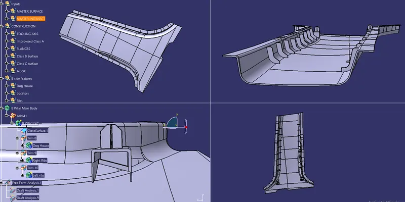
draft analysis is done to verify whether the created solid body will clear the criteria for the prduction of the part bosy in the feature. If any defect in draft analysis, the required surface must be modified.