Week 9 - Project - Master Section Development
B- PILLAR CREATION WITH THE HELP OF MASTER SECTION
The Class A Surface along with the master section is provided to us.
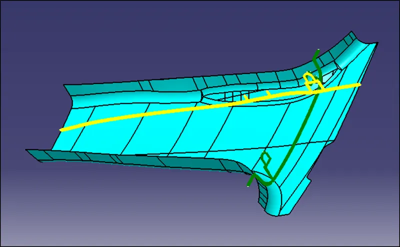
Fig 1. Class A Surface along with Master Section
Check for any discontinuity in the class A surface and if there are any report it to the styling team or solve it locally.
Create a tooling axis for the component. Extract the 4 sides of the doghouse master section and create a line which passes through the exact centre of all these 4 sides.
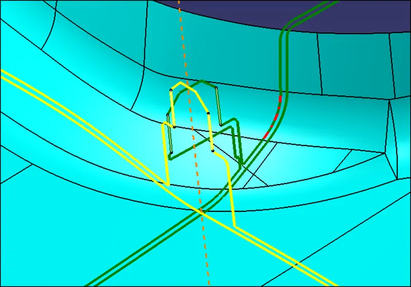
Fig 2. The tooling axis
Next draft analysis of the class A surface is done.
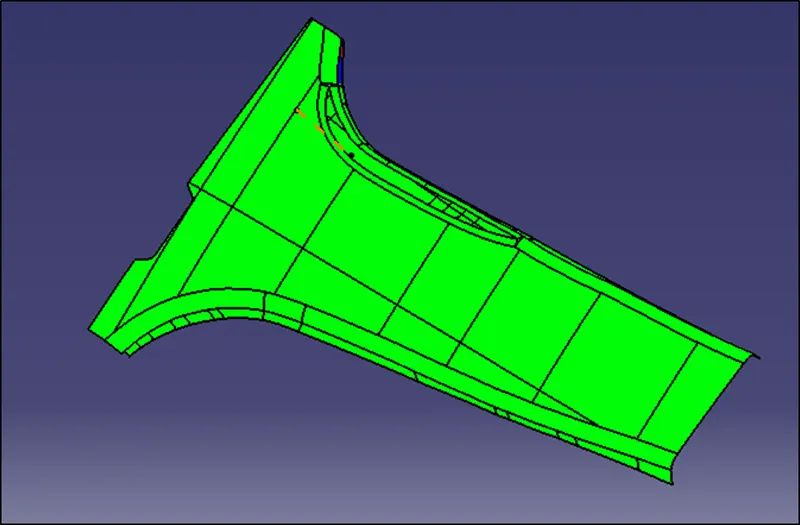
Fig 3. Draft analysis of class A Surface
With the help of Class A Surface create B Surface by measuring the thickness from the master section and offsetting it to get the required thickness of the component.
To create class C Surface, sweep command is used along the draft direction and 3 degrees draft is given. Trim the surfaces to get a complete component. Then in part design, use the command close surface to get a solid component.
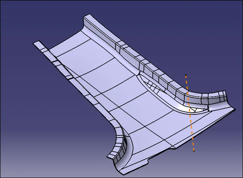
Fig 4. Solid Component
Next the draft analysis of the component is done.
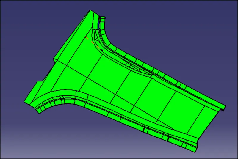
Fig 5. Draft analysis of the solid component
Next the engineering features like dog house and ribs are created. For the doghouse the design rules should be taken care of.
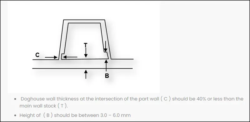
Fig 6. Doghouse design
Extract the inner edges of the master section of the doghouse and then extrude it.
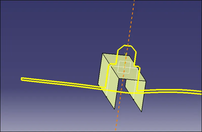
Fig 7. Creation of doghouse.
Select the front limit and back limit of the extrude. For that extract the edges of the other master section provided and the extrude it.
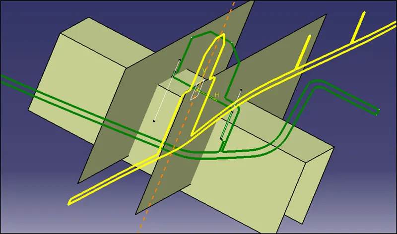
Fig 8. Setting limits for the extrude of the doghouse.
Then trim the surfaces to get the required shape of the doghouse
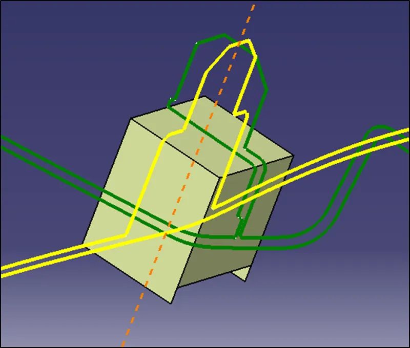
Fig 9. Doghouse body.
Then thicken it to get the solid body.
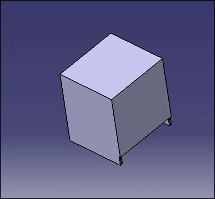
Fig 10. Doghouse solid body.
To create the 4 way locator extract the edges and project it on to the top surface of the doghouse and then extrude it. The height limit is taken with the help of master section.
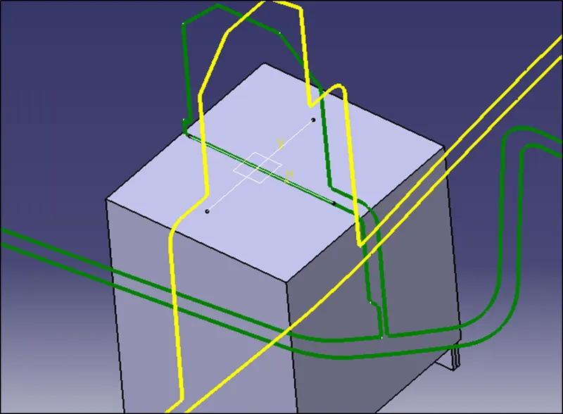
Fig 11. Sketch for 4 way locator
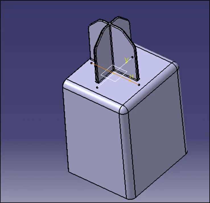
Fig 12. Dog house with 4 way locator.
Apply fillets and 0.5 degree to all the faces of the component.
Draft analysis for the doghouse is done using the main tooling axis. It is clearing all the outside surfaces but the inner surfaces are not getting cleared. For that we need to have a side core tooling axis.
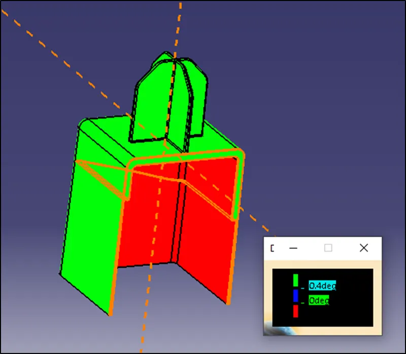
Fig 13. Draft analysis of the doghouse along main tooling axis
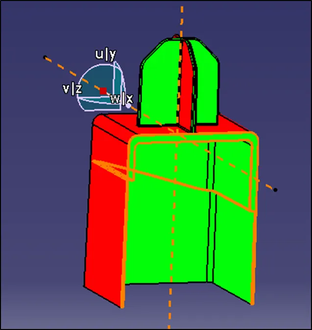
Fig 14. Draft analysis along the side core tooling axis
Next two create the same component on the other side use the option of symmetry. Create a plan eand then use symmetry command. After that use union trim and combine with the B- pillar.
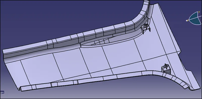
Fig 15. Dog house with solid component
Now to create ribs. The ribs should be at a distance of 50mm from each other. Then by using class B surface split the surface to get the required shape. For the height of the rib offset the class B Surface by 10 mm and the n use the split command.
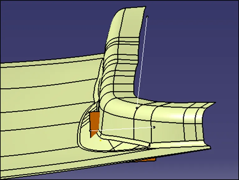
Fig 16. Rib Design.
To create multiple ribs use the command rectangular pattern and apply the fillets and draft of 0.5 degree to each face of the ribs. Then use the Boolean operation of add to add the ribs to the solid component.
Repeat the same steps to create the ribs onto the other side.
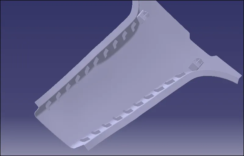
Fig 17. Solid Component
The draft analysis of the solid component is done.
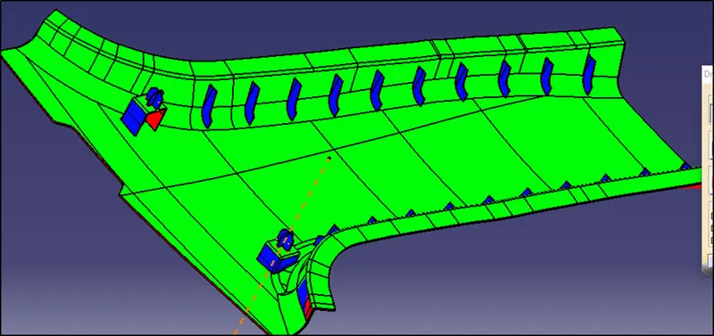
Fig 18. Draft analysis of the solid component along with the dog house and ribs
Some of the views of the B- Pillar.
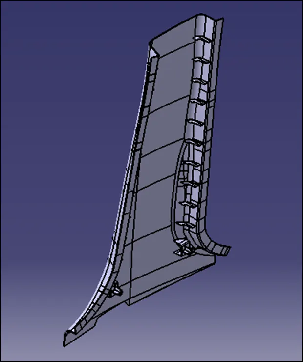
View 1
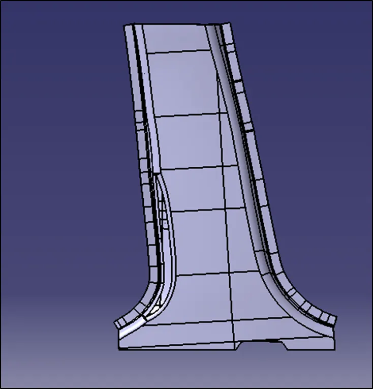
View 2
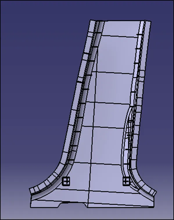
View 3
**********