Week 9 - Project - Master Section Development
TREE STRUCTURE:
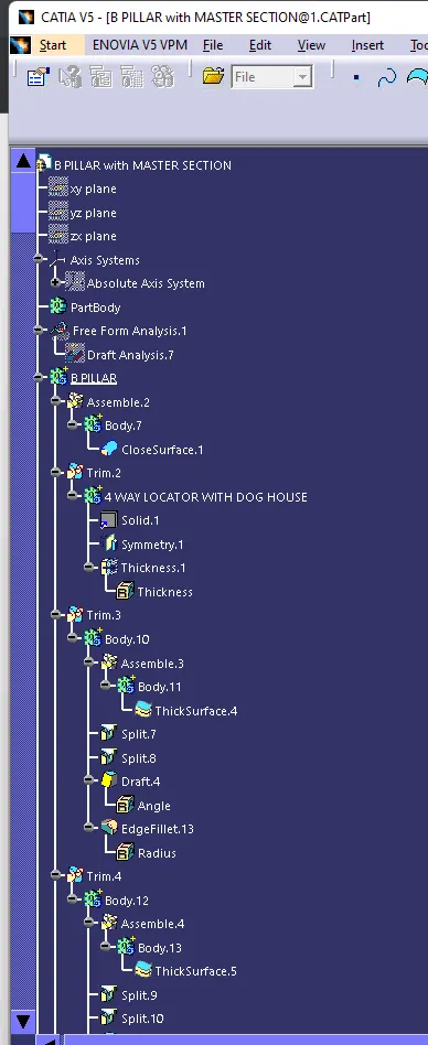
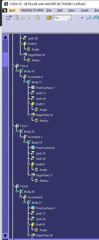
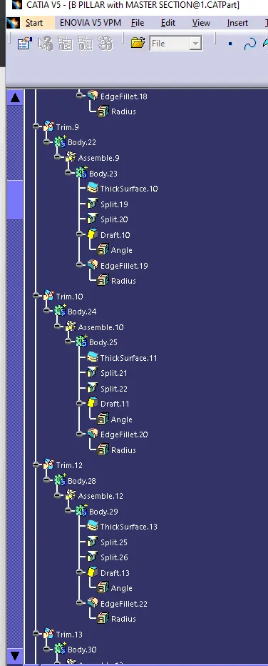
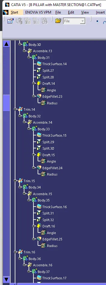
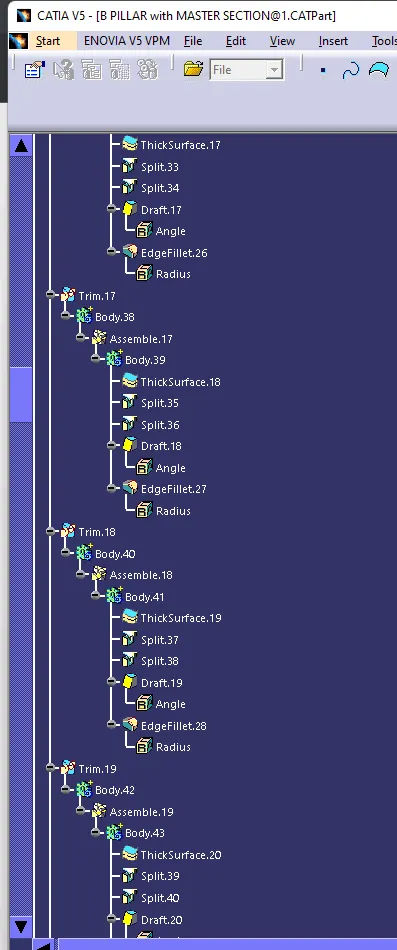
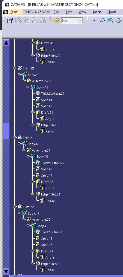
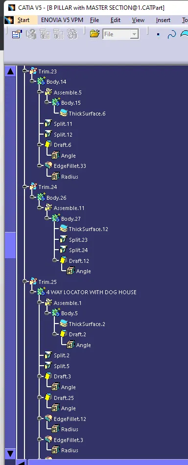
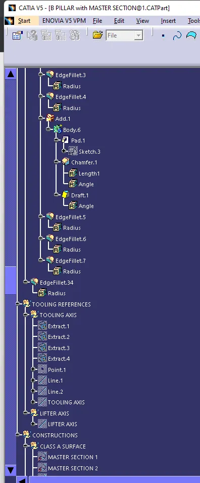
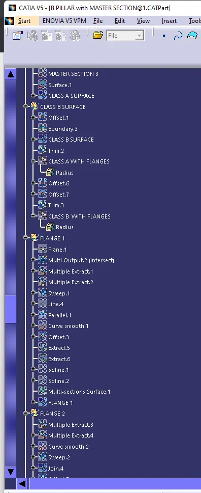
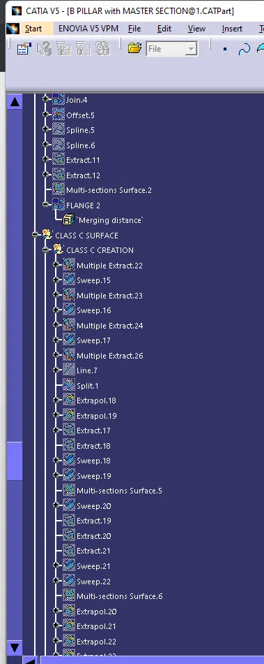
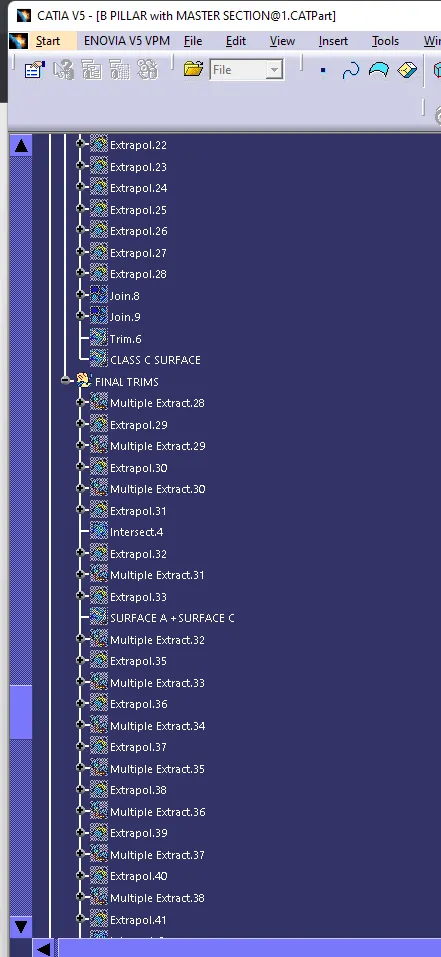
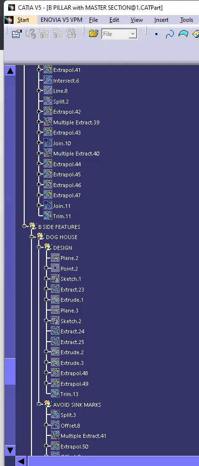
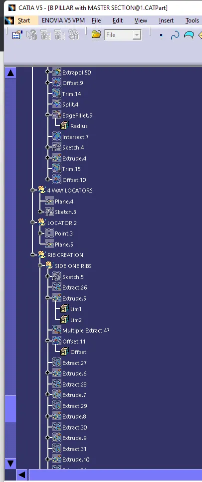
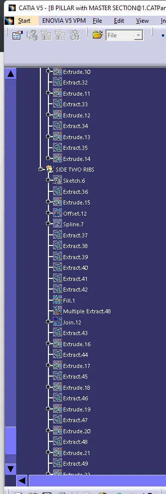
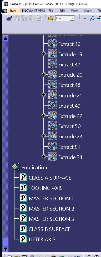
VIEWS:
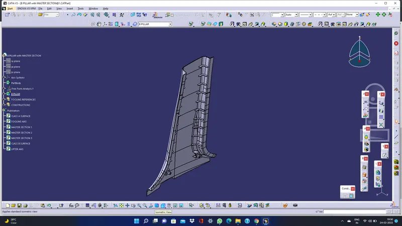
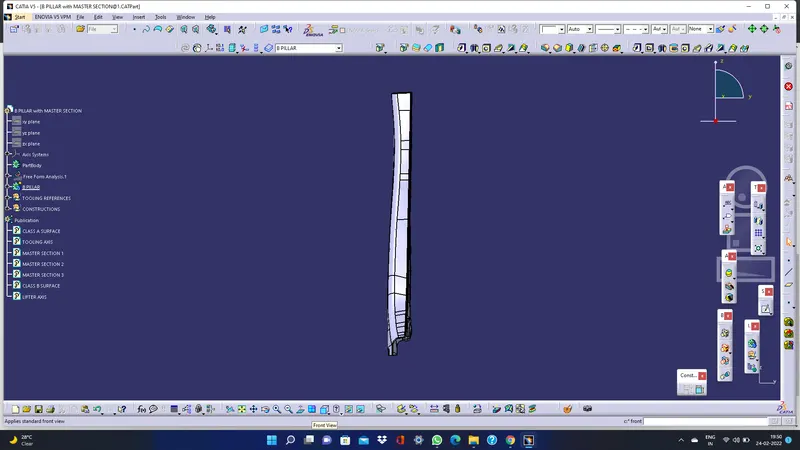
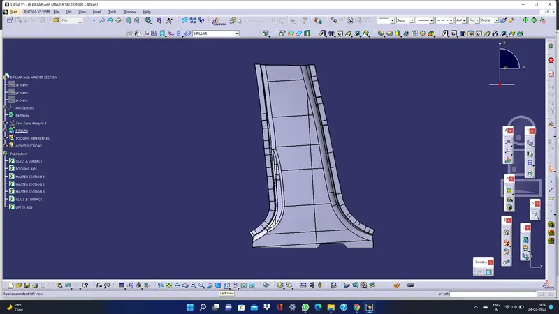
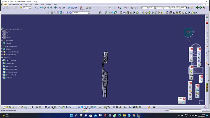
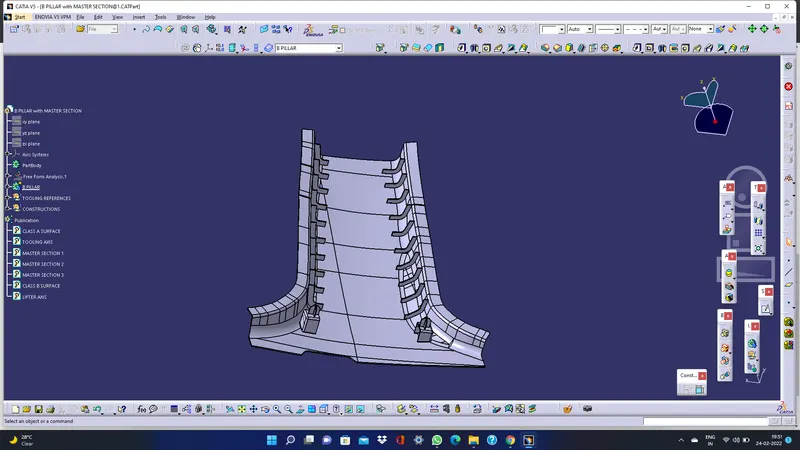
REPORT:
AIM:
To create a solid body of B pillar cover including ribs and locators using catia v5 tool using given A class surface and master section and adding thickness.
INTRODUCTION:
B-Pillar
The B-pillar is the central pillar of the car. This pillar is actually a sheet metal part which is welded in the BIW of the car. The B-pillar trim is attached to the B-pillar and improves the aesthetic look of the car. Mostly the trims are manufactured by the injection moulding process. The design of the B-pillar is carefully done to make the part manufacturable and usable in the interior. While manufacturing a part through injection moulding a lot of defects can occur on the plastic part which will destroy the look of the panel. The design has to made in such a way that all the errors can be rectified.
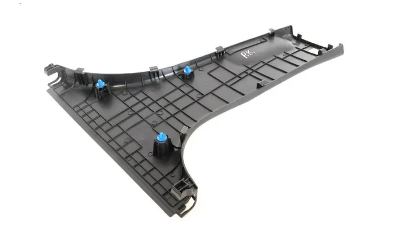
OVERVIEW DESIGN LIFE CYCLE AUTOMOTIVE INDUSTRY
The Stages of Design Life Cycle are
Concept Sketches:
Concept sketches are rough idea of free hand sketch obtained through styling team and will be used to prepare the Model. It is usually done through pen and paper and through the painting software. This is will be used to generate the concept for preparing the model by incorporating various styles and information obtained through the stakeholders
Class A Creation:
After finalizing the concept the sketches are usually worked in software's such as Autodesk Alias to create Class A Surface
Clay Moulding:
The Class A Surface is concurrently worked by clay modelers to brainstorm and benchmark the styling of the product and later the Concept is validated by bringing up a rough clay model and then it is passed on to the Design team for the preparation of New Product Design (NPD) CAD.
NPD CAD:
This where the development of surfaces to parts in CAD kick off and Design engineers involvement is vital in this stage.
The Designers will work on the Input Class A surfaces which are validated from the Feasibility team
The procedure followed in creation of the plastic New Product Design are
- Tooling Axis
- B Surface Creation
- C Surface Creation
- Closed Body Creation • Draft Analysis
PROCEDURE:
1) Input Given:
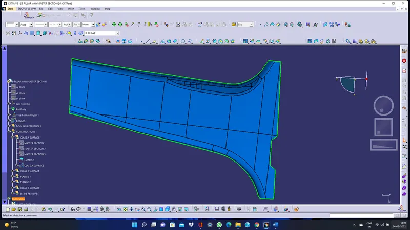
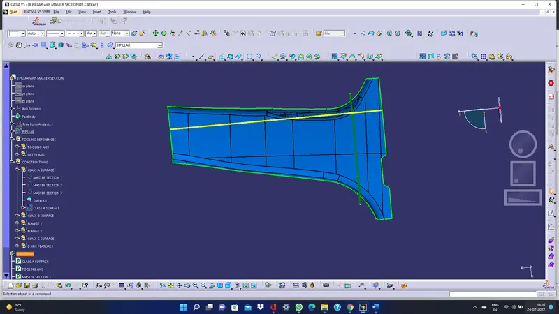
2)Tooling Axis
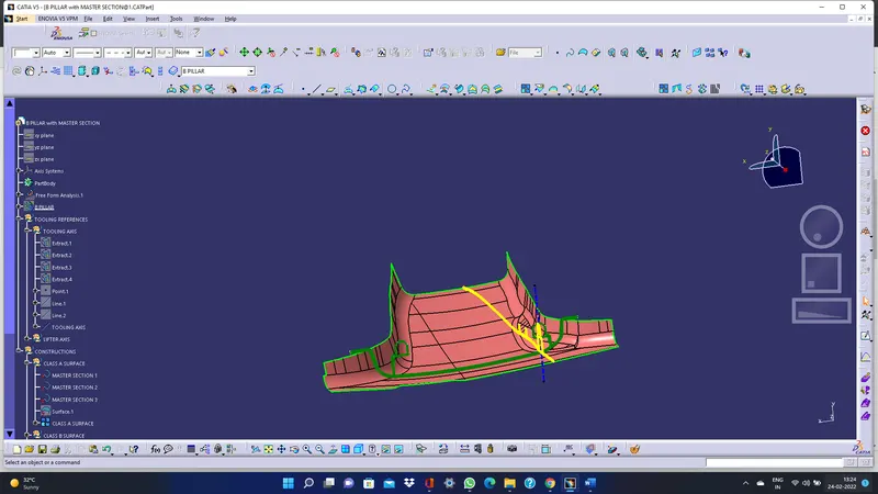
Tooling axis is nothing but the direction in which the core and cavity opens and closes. Design engineer works is to analyse the Class A surface and find out the best possible tooling direction keeping in mind all the draft angle is with respect to the tooling axis so that the component can be easily ejected from the moulds.
3) A Class Surface
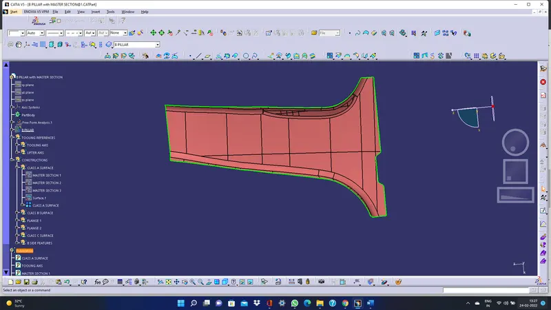
In automotive design, a class A surface is any of a set of freeform surfaces of high efficiency and quality. Although, strictly, it is nothing more than saying the surfaces have curvature and tangency alignment - to ideal aesthetical reflection quality, many people interpret class A surfaces to have G2 (or even G3) curvature continuity to one another. Class A surfacing is done using computer-aided industrial design applications. Class A surface modellers are also called "digital sculptors" in the industry. Industrial designers develop their design styling through the A Surface, the physical surface the end user can feel, touch, see etc.
4) B Class Surface Creation
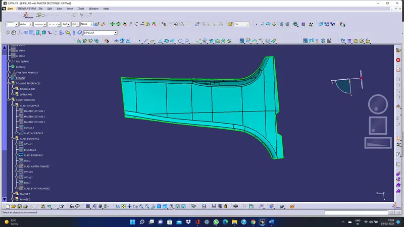
Represent internal and/or functional surfaces. This cluster exemplary includes derived surfaces created by offset operations from class A surfaces to define the thickness of material. In this file it is important to link class B surfaces geometrically to enable an adaptation to class A surfaces automatically in case of styling change.
After creating the tooling axis, B surface is to be created which is nothing but the surface parallel to the A surface. B surface contains all the fillets and the edges which the A surface contains.
5) C Class Surface Creation
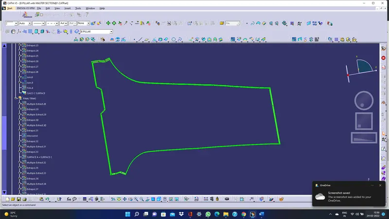
Class C Surface is swept along the boundary of the Class A at an angle perpendicular to the CLASS A surface with respect to the tooling axis direction with a draft angle of 3 degree.
6) Joining CLASS A, B and C Surfaces to get a Closed Surfaces
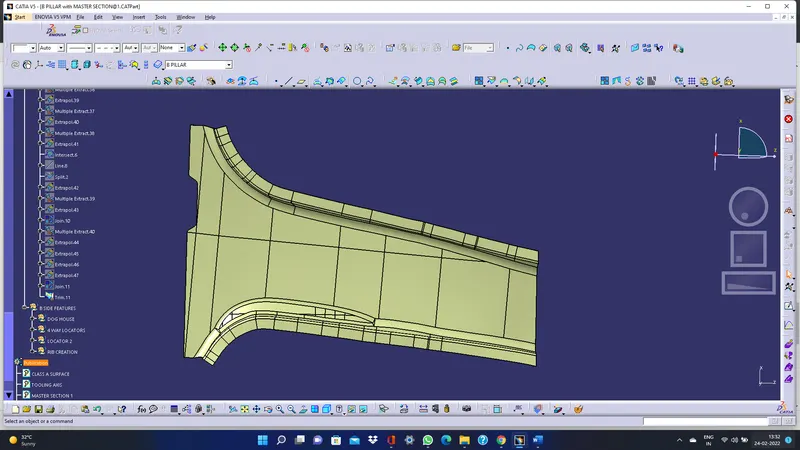
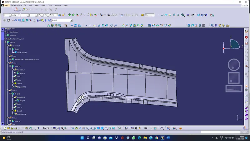
After finishing all the 3 surfaces, join the class A and class C surface together using the Join command. Now, the joined surfaces are then trimmed with class B surface to form a closed surface.
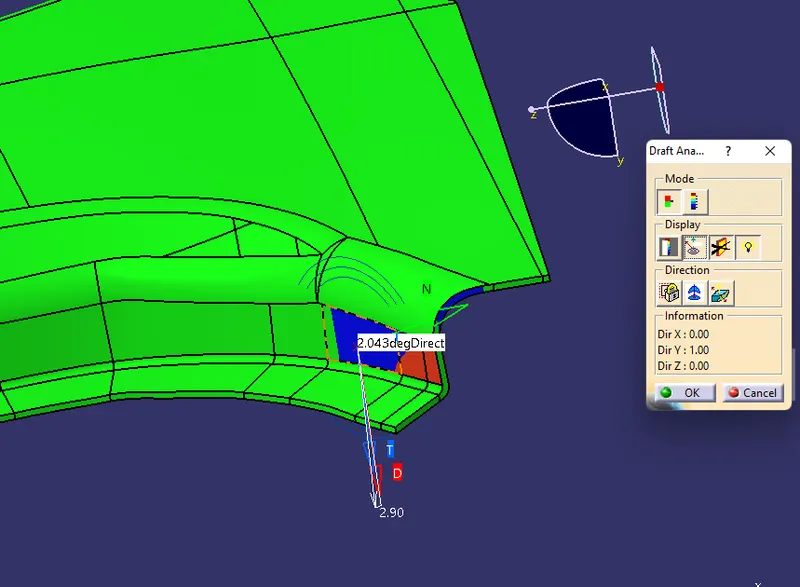
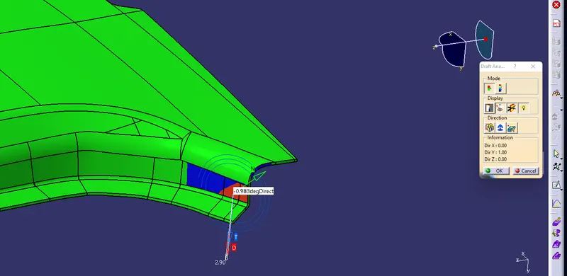
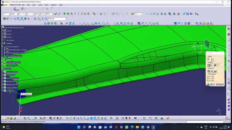
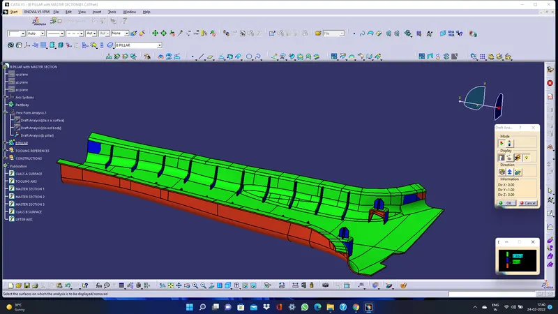
7) Draft Analysis
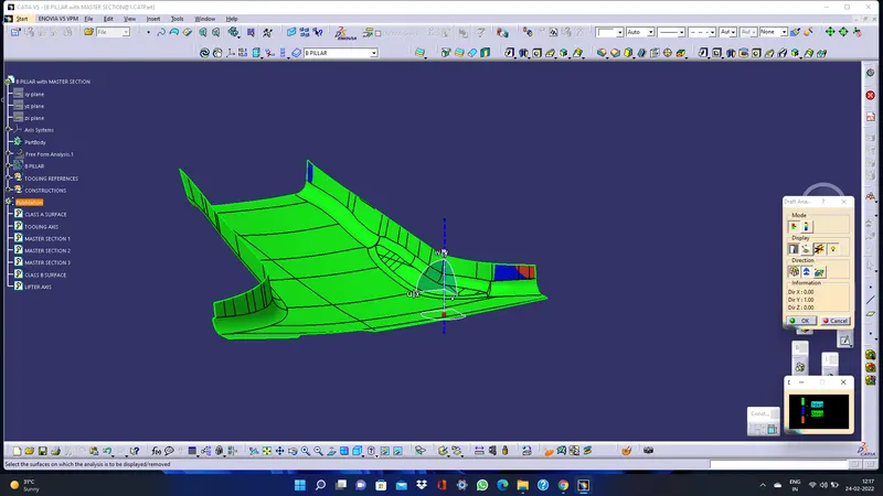
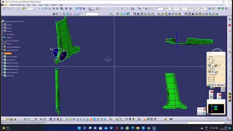
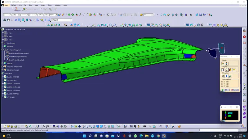
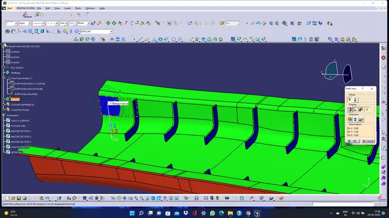
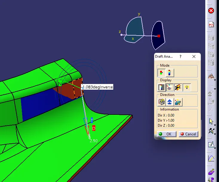
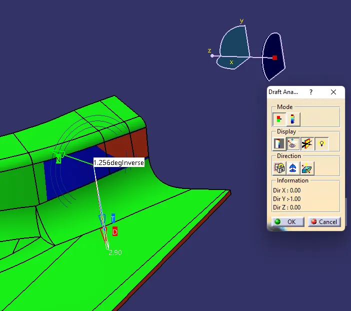
The Draft Analysis command enables you to detect if the part you drafted will be easily removed. This type of analysis is performed based on colour ranges identifying zones on the analysed element where the deviation from the draft direction at any point, corresponds to specified values.
Draft angles are very important in thermoforming product design. If the product is formed onto a female or negative mould, it shrinks away from the mould sidewalls. As a result, true female or negative products can be thermoformed with vertical walls having zero draft angles. Parts Cannot be ejected from the tool if it is at 90 degree surface for the reason, A small Draft angle is to be provide for each and every surfaces of the Component in order to easy removal of component from the moulds without any defects. Draft is the angle in which the part is tapered to allow it to release. Most of the part require minimum 1/2 degree to 1 degree however 3 degrees are widely accepted in plastic component design. Draft Analysis is the technique used to analyse weather our designed product are manufacturable with required conditions or not.
The below shown faces do not clear a minimum draft of 3mm.
CLASS A DRAFT ANALYSIS
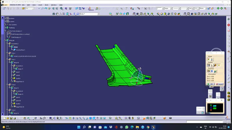
CLOSED BODY DRAFT ANALYSIS
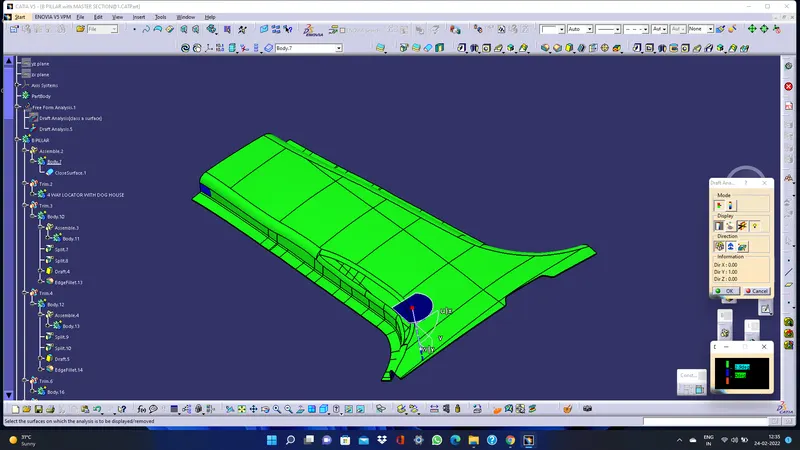
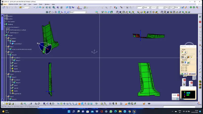
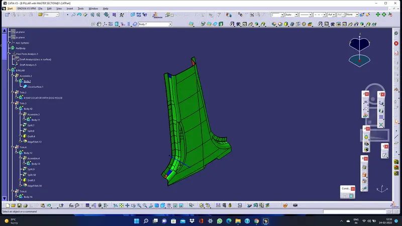
B PILLAR DRAFT ANALYSIS:
8) Creation of Ribs, Dog house and 4 way locators:
4-way locators mean you prevent movement at 2 axis (+X, -X, +Y and -Y) on the plane. Generally you have cylindrical pin on the fixture and circular hole at workpiece part.
In any kind of assembly before fixing the part to the mating part we need to fix the position of the part with respect to the mating part. In these cases we need to follow some engineering principles. In this project we are going to follow the 3-2-1 Principle. Any Part which has to be fixed during welding or machining process has to be fixed is having 12 degrees of freedom.
- Translation Movement along X Axis
. Translation Movement along Y Axis
- Translation Movement along Z Axis
- Rotational Movement along X Axis
- Rotational Movement along Y Axis
- Rotational Movement along Z Axis
Dog House:
Create the dog house as per the design rules and give the required draft angle.
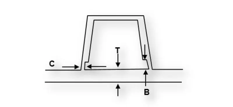
- Doghouse wall thickness at the intersection of the part wall (C) should be 40% or less than the main wall stock(T).
- Height of (B) should be between 3.0-6.0 mm.
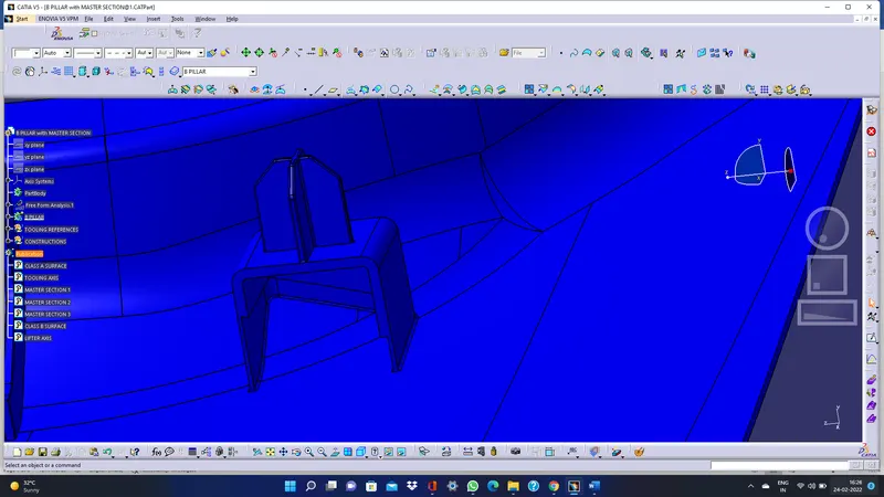
Dog House with 4 way Locators
Ribs:
Create the ribs as per the design rules and give the required draft angle. Ribs are created to increase the stiffness and strength of the surface.
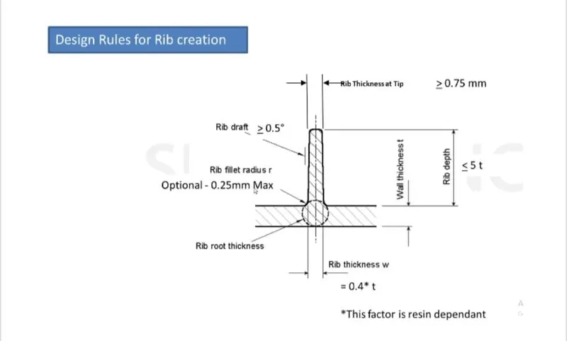
B pillar ribs
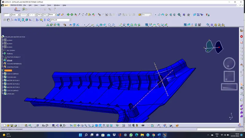
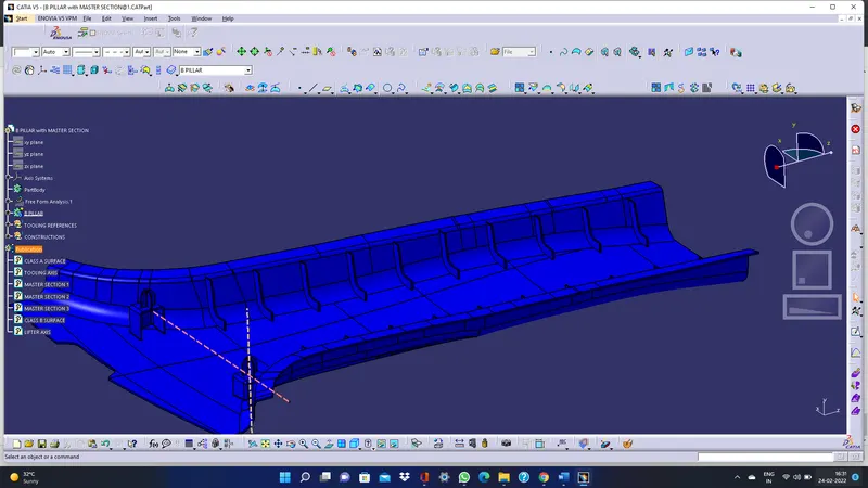
9) Draft Analysis for B side features.
Create the side tooling axis to check the draft analysis for the dog house. Also check the draft for other B side features using the main tooling axis.
Side Tooling Axis:
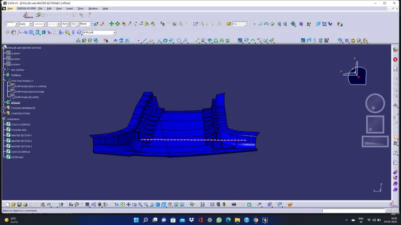
Draft analysis wrt side tooling axis:
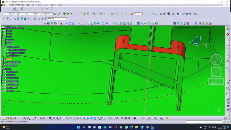
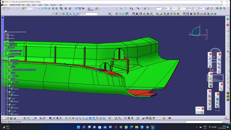
Draft analysis wrt main tooling axis:
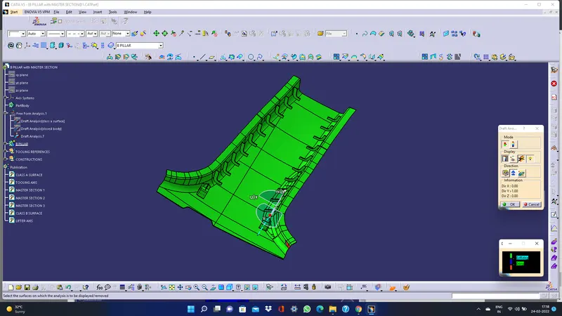
We can see that, the draft is clearing for all the B side features wrt the main tooling axis as well as the side tooling axis.
Final B pillar model
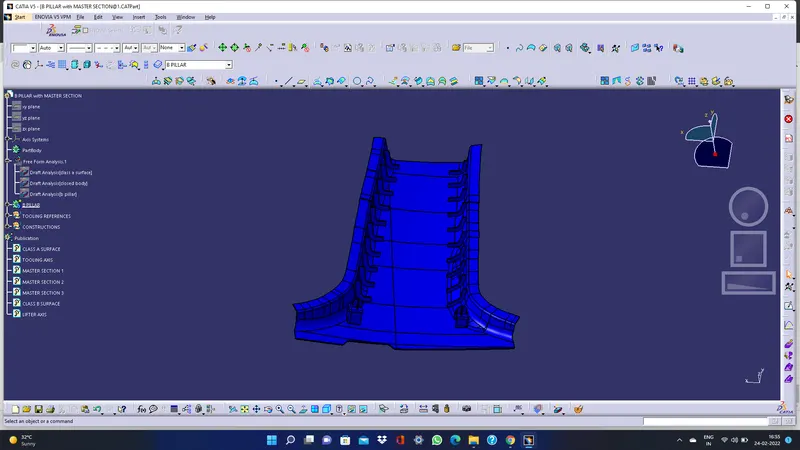
Result:
- Class A, B and C surface was created as per the automotive standards using catia v5software.
- Draft analysis was performed for the built model and it could be seen that the draft was under permissible limit for the manufacturing of the component.
- B side features were created for the component as per the design rules.