Week 9 - Project - Master Section Development
Having easier ejection from the mold may seem like a minor concern, but draft is crucial to manufacturing parts that meet your quality standard. Without draft, major problems can arise in the injection molding process that increase the time and cost of production.
When no draft is designed into the part, problems can come from friction and vacuums. These issues can damage both your part and even your mold in extreme cases. These problems are a direct result of having insufficient draft. Because plastic shrinks as it cools, portions of the part may pull away from the mold while others grip the core. If there is no draft angle that allows a simple push from the ejector pins to pop the part out of the mold, the part’s surfaces will often drag along the mold as it is being ejected. This friction between the two surfaces can cause scratches or gouges in your part and affect the appearance. This is particularly troublesome if your part is being molded with a surface finish or texture. The friction will scrape away texture and leave you with many rejected parts.

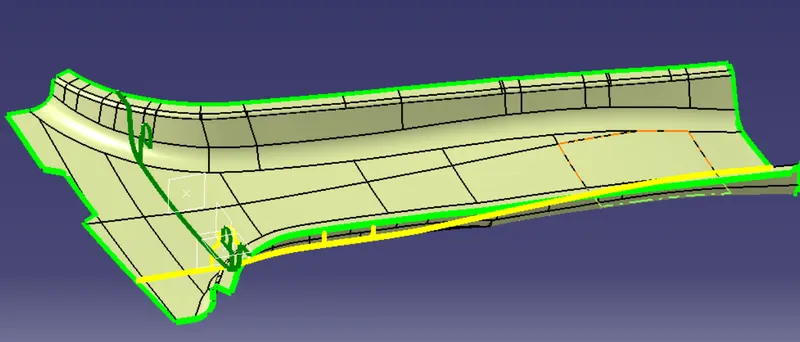
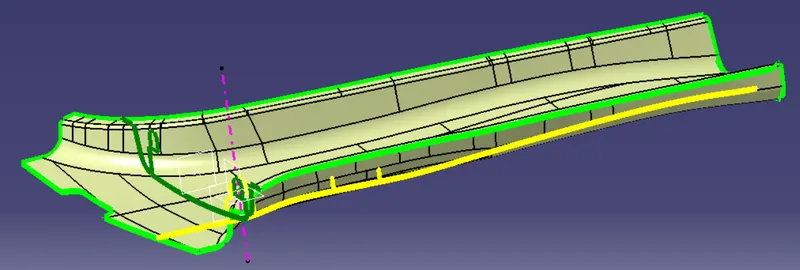
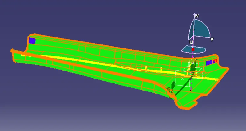
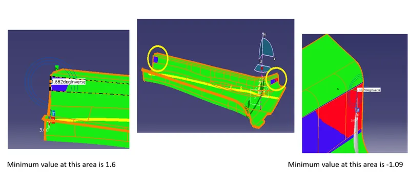
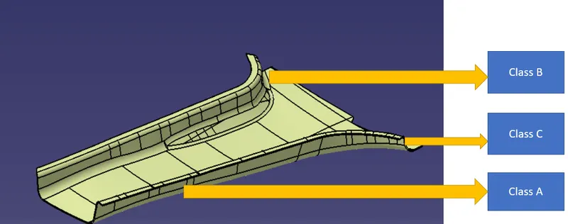
Designing the class B surface from the given class A surface is the next step to be followed
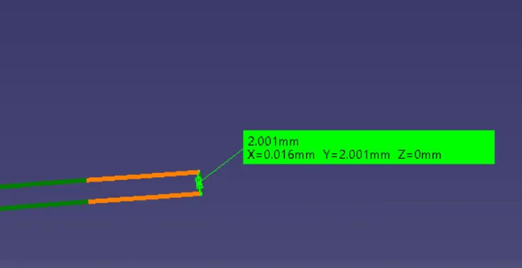
- As there is variable fillet in the class A surface we offset the whole class A surface by 2mm and 2mm was cosidered as the thickness of the given master section was 2mm.
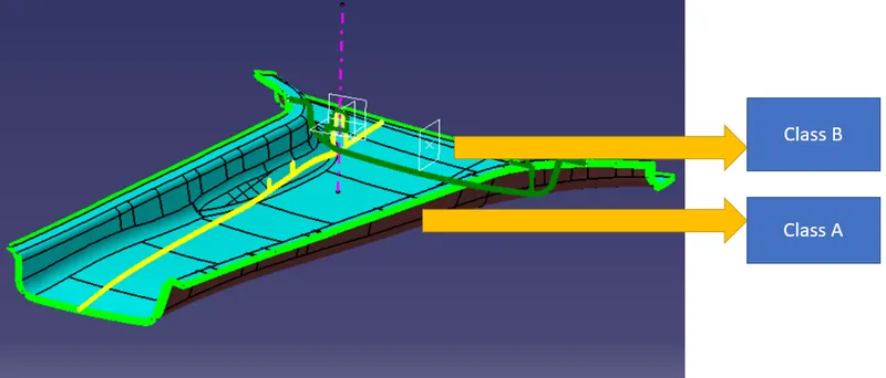
Class C surface
Class C surface are once which lies between the Class A and B surface . while creating the class C surface we have provided the draft greater than 3 degree in such a way that the parting line lies at the B surface. And this is done to prevent flash on the Class A surface.

Engineering Features
DOG HOUSE
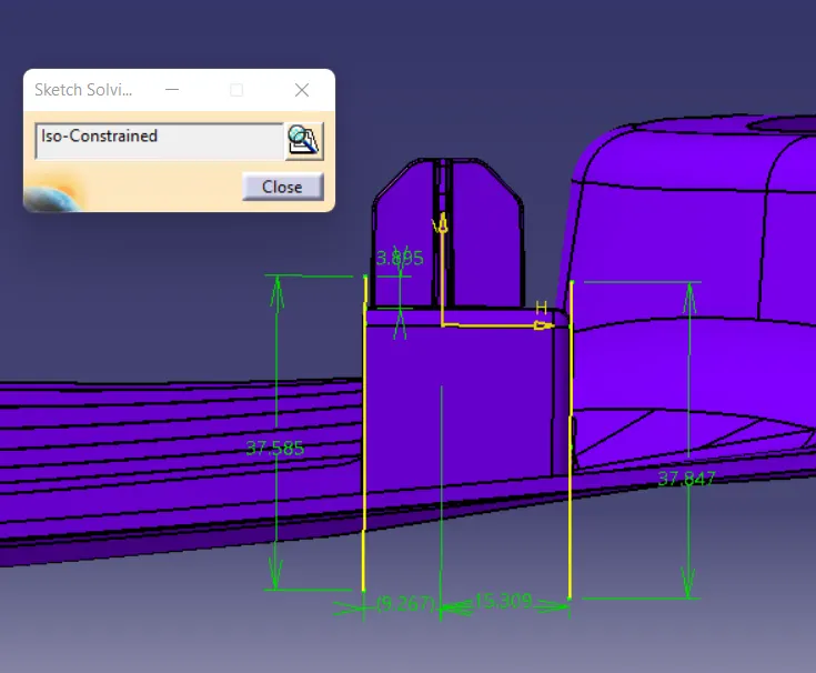
Dog houses are used as supporting feature. Dog house is a feature that helps to avoid sink marks. They are certain locations where it is not possible to use engineering features such as locators, screw bosses etc, directly from the surface due to the desing constrains hence it is necessary to use dog house.
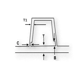
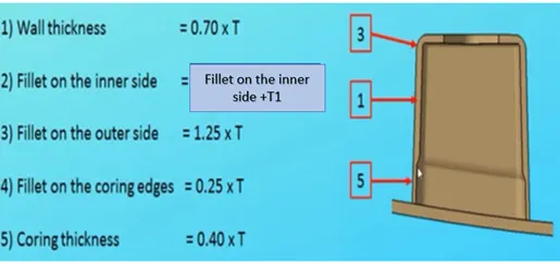
T1=Maximum thickness of the dog house
Dog house wall thickness at intersection of part wall (C) should be 40% or less than main wall stock (T).
Height of (B) should be between 3.0 - 6.0 mm.
Dog house draft to die Minimum draft (D) for dog houses 1.5 degree to die draw.
If a slide is being considered, this requirement can change to 3 degrees minimum.
Dog house height
Minimum height (H) of dog house is 6mm. Less than 6mm causes weak steel condition.
3: 1 ratio of steel width to height, 2: 1 is preferred.
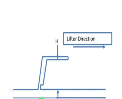
Dog house width
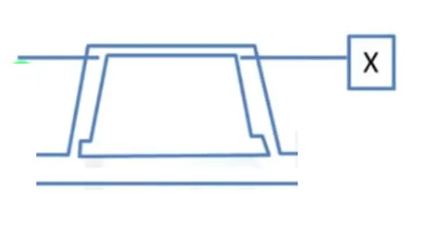
Minimum dog house width (X) for doghouse is 12mm.
3: 1 ratio of steel width to height, 2: 1 is preferred.
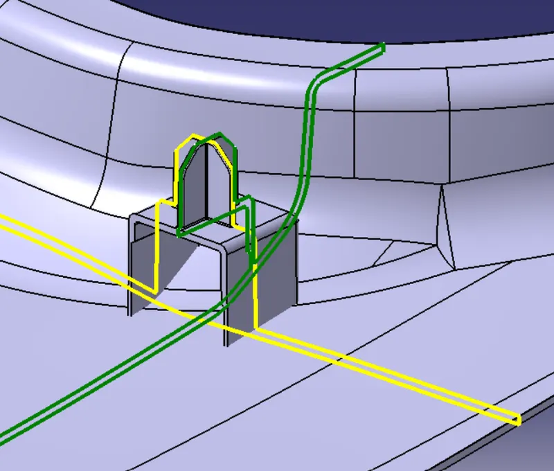
Designing of the Dog house and the 4 way locators
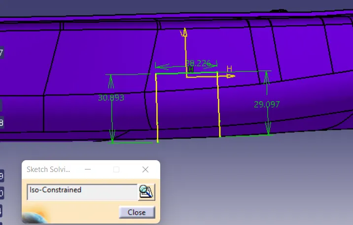
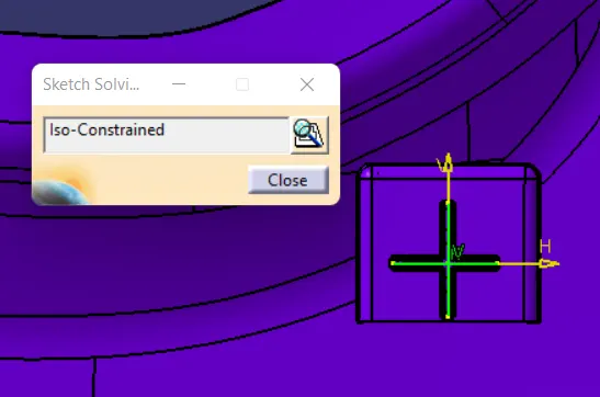
Following the design guidelines and with reference of the mastersetion provided the dog house can be designed
RIBS
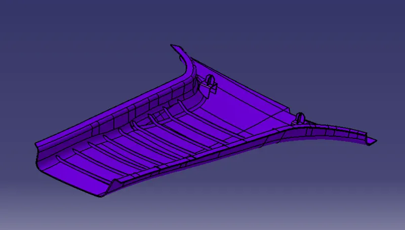
Ribs provide a means to economical stiffness and strength in molded parts without increasing overall wall thickness.
- They also facilitate locating and arresting components of an assembly;
- Providing alignment in mating parts
- Acting as stops or guides for mechanisms
Procedure(All dimensions are in mm)
A) Rib Design guidelines
Nominal wall thickness of a plastic component: 2mm
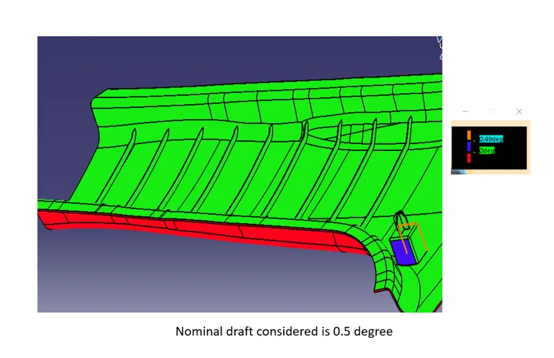
A deviation of + -30% from the wall thickness is accepted Ideal draft for a component is 3 deg Minimum 0.5 deg accepted in ribs.
Example for 3 mm thickness 2.1 mm is minimum 3.9 mm maximum accepted
If we go above 3.9mm or below 2.1mm then it can lead to sink marks and at time flow lines too
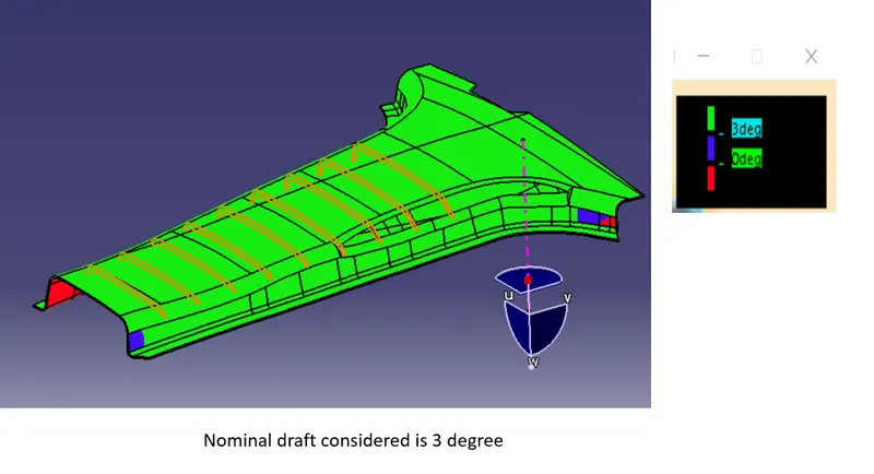
Ideal draft for the components is 3 degrees
Minimum 0.5 deg accepted in ribs
For the surface where we need secondary operations for good surface finish in this area, we need to have 7-degree draft.
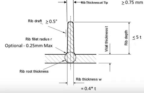
Thin - walled parts (<1.5 mm) can often tolerate ribs that are thicker than the percentages in these guidelines.
On parts with wall thicknesses that are 1.0 mm or less, the rib thickness should be equal to the wall thickness.
Rib thickness also directly affects moldability. Very thin ribs can be difficult to fill. Because of flow hesitation, thin ribs near the gate can sometimes be more difficult to fill than those further away.
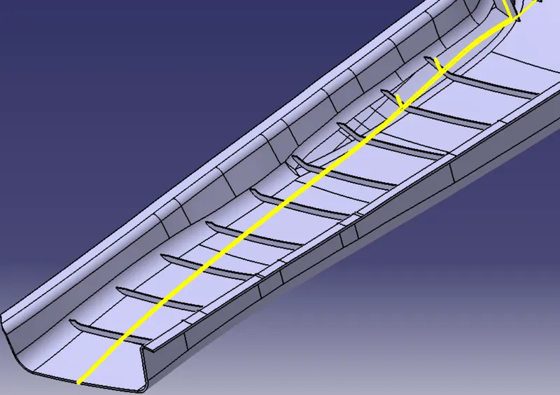
Designing of the Rib
Following the design guidelines and with reference of the mastersetion provided the rib can be designed
Draft Analysis after designing the class B Class C surface and the engineering features
Class A surface analysis
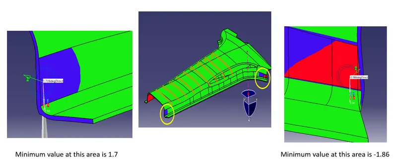
Class B surface Analysis
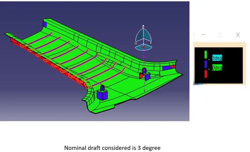
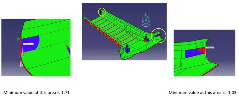
Class C surface Analysis
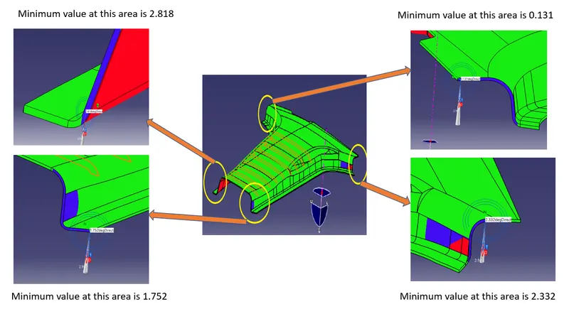
Engineering Features Analysis
Dog house and 4 way locator analysis with respect to main tooling axis
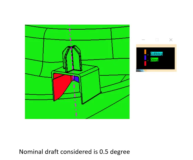
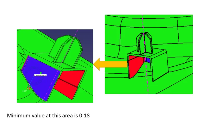
Dog House analysis with respect to slider tooling axis
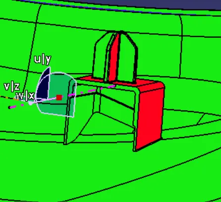
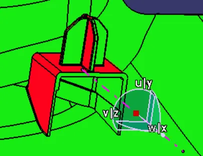
With respect to slider tooling axis there are no negavtive draft for the dog house
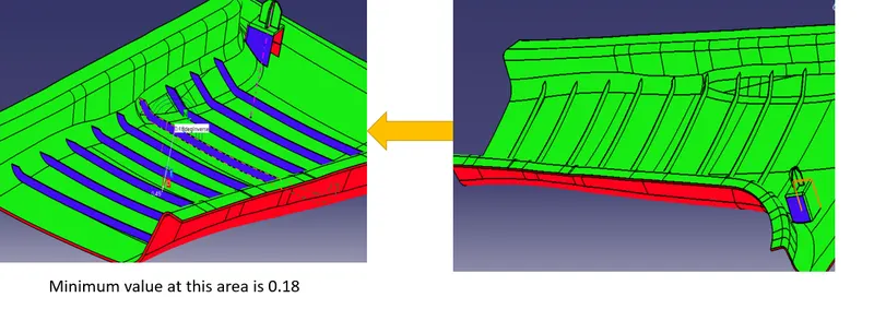
Ribs analysis with respect to main toolin axis