Project 2
Aim
To design mold for CPU fan bezel.
Introduction
A mold is a hollowed out block that sets the shape of the product being made. It can be made of different materials, the most common of which are aluminum, steel, alloys and copper
Procedure to design the mold tool
If there is no sufficient draft given for the part, it will damage the mold hence it is necessary to modify. Me considering as a Mold Engineer it must be reported to the product design team to modify the part. once it is revised, we can move forward to design the mold.
Procedure to followed are
1) Draft Analysis- to check if sufficient draft is given.
2) Scaling - considering material as ABS (shrinkage - 0.6%).
3) Parting line- it will be used to create a line at the intersection of the core and cavity.
4) Shut off surface - to shut of all the hole in the model.
5) designing the core and cavity block.
6) designing sliders to solve the problems of undercut.
7) designing the ejector pin and plates- this is required for the ejection of the part from the core.
8) designing the runners and gates- the injected materials enter through runners and gate.
9) air vents- air vents must be created to remove the air present in the mold, and this is done to prevent from overheating and to prevent burn marks.
10) cooling system it is necessary to cool the part adequately by doing so we can prevent the warping of the part.
Here are the tools used for the design.
a) mold tools
draft analysis, parting line, shut off surface, split line and core.
b) direct editing
move copy bodies, move face, delete body, split, combine and fillet.
c) surfaces command
Surface trim, Planar surface, offset surface, surface knit, surface cut.
d) under features
Extrude boss, extrude cut, hole wizard, sketch driven pattern.
e) others
float ,mate, move component- Rotate component ,weldment
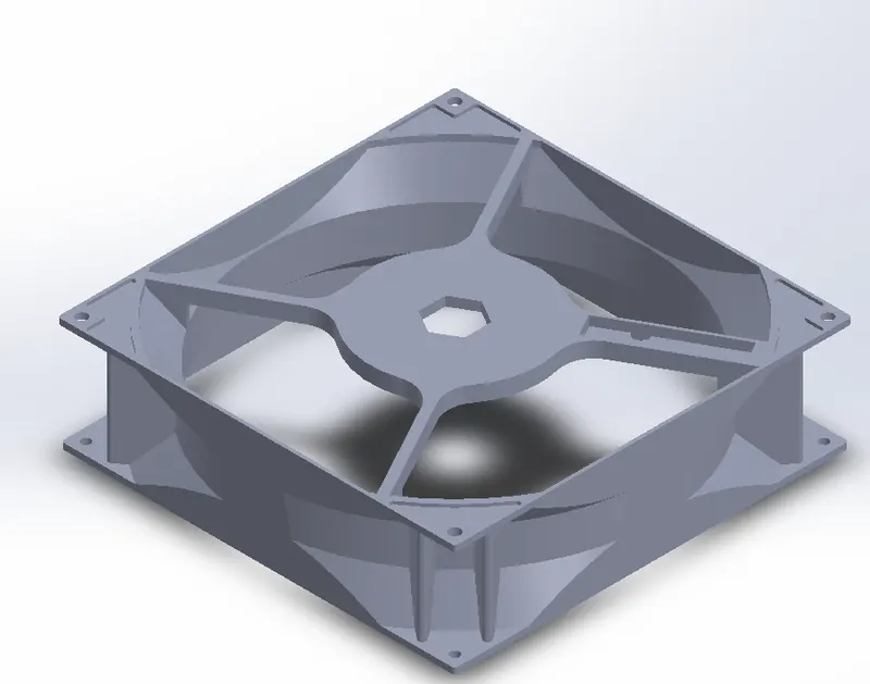
Given plastic component for which the mold has to to be designed
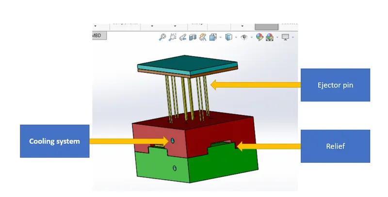
Screenshots of the mold designed
Cavity
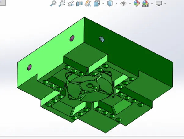
Cavity- The cavity is the female part which forms external shape of molding.
Core with the other components of the mold
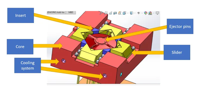
Core-The core is the male part which forms the internal shape of molding.
Ejector Pin- They apply a force to eject a part from the mold, and in some cases can leave marks. Once the mold is opened, the pins extend into the mold cavity, push the part out, and then retract, allowing the mold to close and be refilled.
Inserts-in certain case when the depth of the cuts in the designed mold is greater and as it can be manufacturable in the real scenario due to the absence of the tool in this condition the inserts will be designed
Relief- the surface is perpendicular (at a 90-degree angle). So, as the core block moves away from the cavity, it will rub the cavity block and will damage the mold block as time passes. Generally, you should try to avoid steel to steel rubbing in mold blocks. Hence, a relief component is provided to prevent such damages.
cooling system- it is necessary to cool the part adequately by doing so we can prevent the warping of the part.
Slider
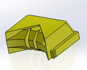
slider
Sliders-sliders are designed when there is presence of undercut in the plastic component
Conclusion
The mold for the given plastic component was designed successfully