Master Section Development
Aim: To design the B-Pillar using the given Master sections as per the industrial standards and design rules.
Project Overview:
B- Pillar is the vertical support located between front and rear doors of any typical car. We create the solid component of the same from a given Class-A surface. After designing the solid component with proper drafts and design rules, we create B-side features on it in order to mount it on the door surface. Finally we perform the draft analysis on the component in order to verify our design.
Workbench and its Toolbar used:
Generative Shape Design Workbench
- Surface Toolbar
- Wireframe Toolbar
- Operation Toolbar
Part Workbench
- Surface Based Feature Toolbar
Theory:
Tooling Axis - Tooling Axis is the direction in which the component will be ejecting after the molding process is completed. The rules of selecting an optimum direction of tooling axis for any particular component is as follows :-
- The direction of the tooling axis should be clearing the maximum number of portions of the component once the molding process is completed.
- The direction of the tooling axis should be selected such that the number of side cores required should be minimum, as inserting side cores causes a rise in production cost.
Drafting - Draft is the inclination given to any particular plastic component’s cavity walls in order to achieve easy ejection, once the process is completed.
- Consider that the draft angle between the plastic component and the core is zero.
- When the molten plastic inside the cavity cools, it sticks to the walls of the core.
- During such zero draft condition, the ejection of the plastic component causes friction between them which might bring damage to both the core and the component.
- This damage further leads to inefficiency in the production & also affects the product’s surface finish.
- Hence, a minimum of ½ to 1 deg draft is provided to help in releasing the component.
- However 3 deg draft is widely accepted as a norm in the industry.
Prerequisites before creating the tooling axis and performing draft analysis-
- Ensure that the Class A surface imported should be a single surface.
- This can be checked using the Boundary tool in the Operation Toolbar.
- If the surfaces are disassembled, join them using Join command which is also found in the Operation toolbar.
Creating any component from Class A Surface ( Overview ) -
- Decide a suitable tooling axis direction and create the Tooling Axis.
- Perform Draft analysis for analyzing whether the drafts on the component follow the industry standards.
- Create another surface ( B Surface ) offset to the Class-A Surface. The offset distance should be equal to the thickness of the component.
- Create a C- Surface ‘Sweeping’ the boundary of Class-A -Surface along the Tooling Axis.
- Trim Class- A surface with B-Surface and C Surface to create a closed surface.
- Finally create the solid part from this surface to obtain the desired component.
Pillars:
Pillars are vertical supports or nearly vertical supports provided to the car’s window area. They are designated to be -A,B and C. As per the alphabetical order, A-Pillar is the front support, B-pillar is the middle support and C-Pillar is the Rear support. In larger cars they also have a D-Pillar for the rear most support.
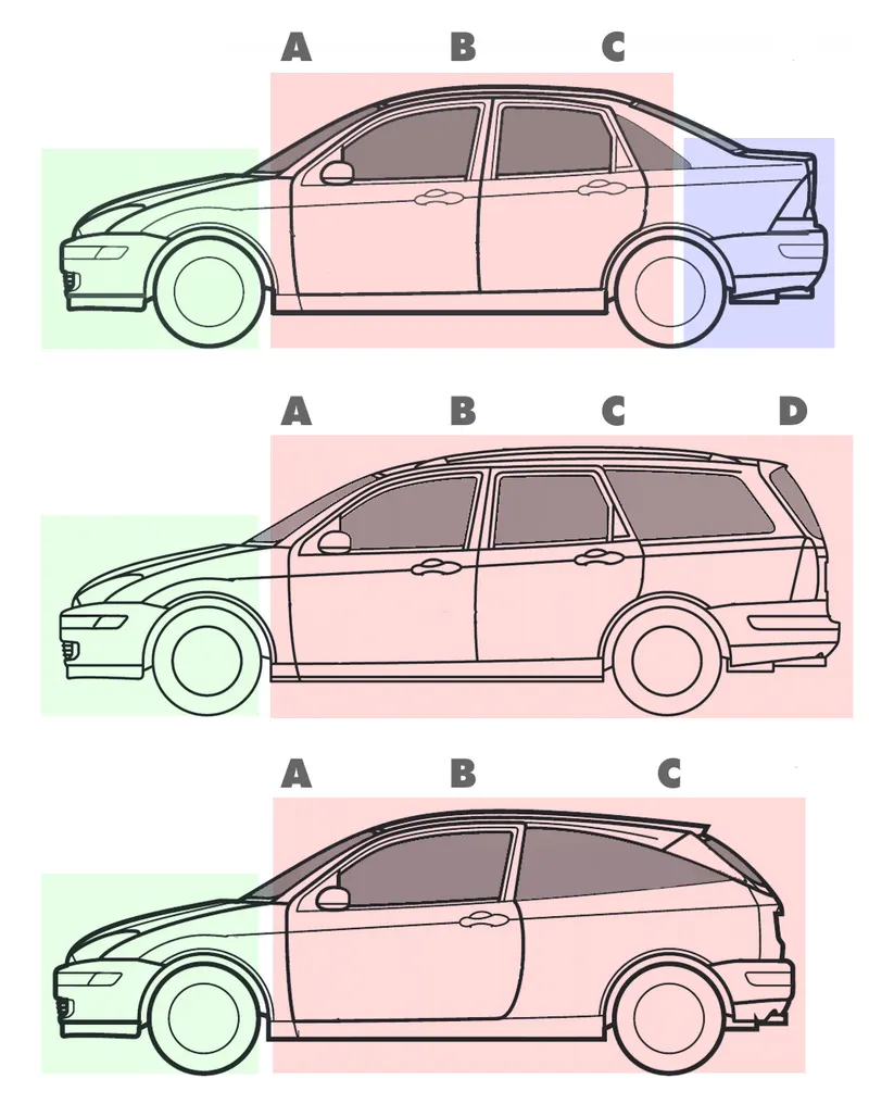
Procedure:
I] Troubleshooting the problems in the imported Class-A Surface:
- The Class A Surface was disassembled when imported which violates the rule for proceeding further.
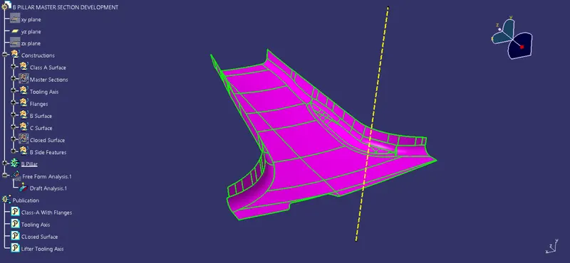
- Use Join Command from the Operations Toolbar to join these surfaces together.
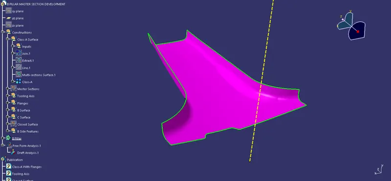
II] Analyzing the master Sections:
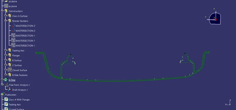
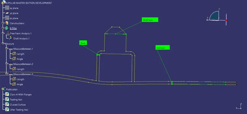
Thickness of the component = 2.00 mm
Thickness of Dog house = 2.00 mm
Length of 4-Way locator = 16.00 mm
III] Creation of Tooling Axis:
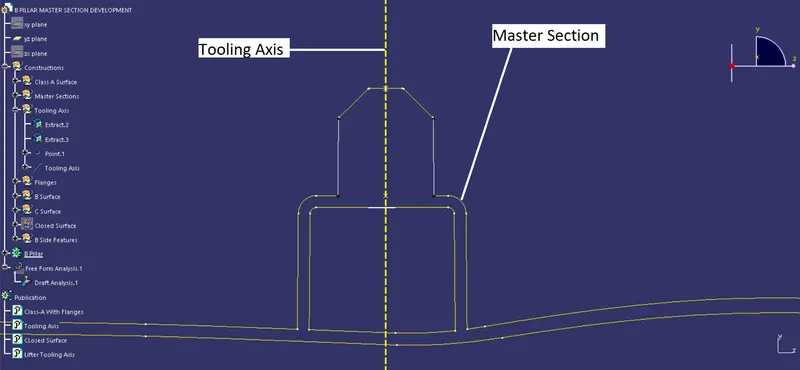
- We can follow the reverse engineering approach here.
- As per the master section we have a section of the locator and the dog house.
- These B-side features will be manufactured along the tooling axis.
- So we extract the lines from the master section and create a midpoint.
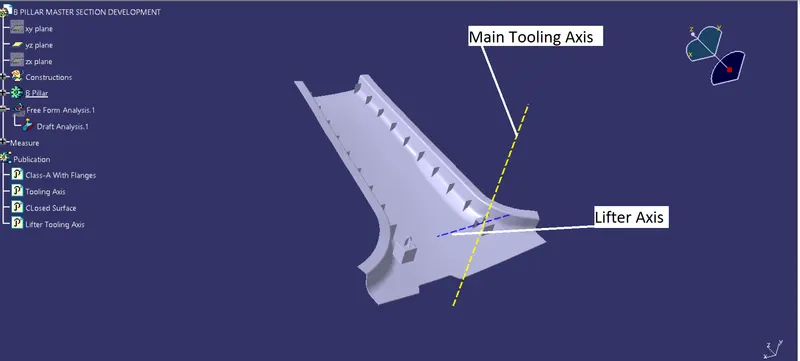
- Creating a line along that point will give us our tooling direction.
- Also in order to clear the dog house, we create a lifter axis normal to the open end.
IV] Creation of Flanges:
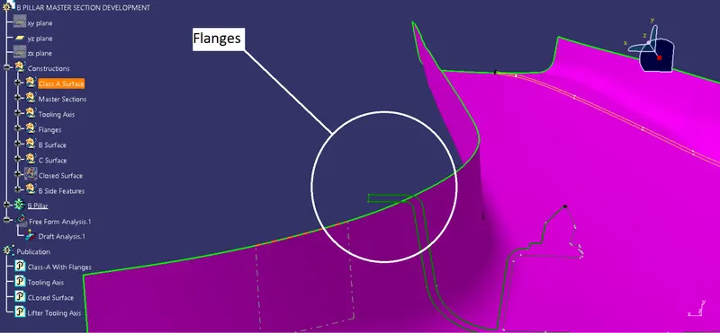
- As per the master Section we have flanges on the Class-A surface which need to be formed.
- So we create them using the Sweep with reference surface tool.
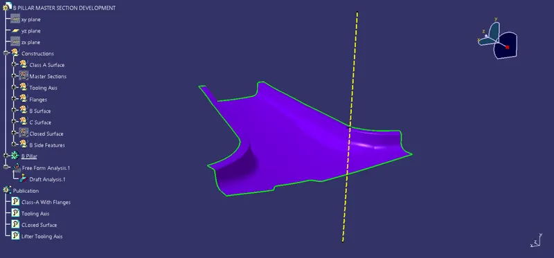
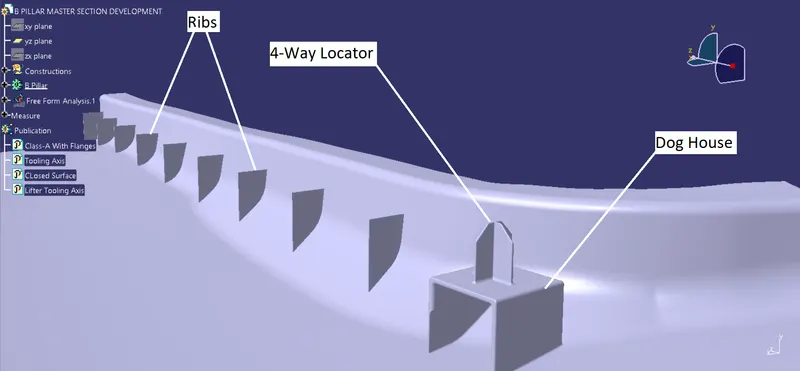
V] Designing the Attachment Features:
Following the design rules and master section we design the Dog house, ribs and the 4-Way Locators
VI] Solid Formed:
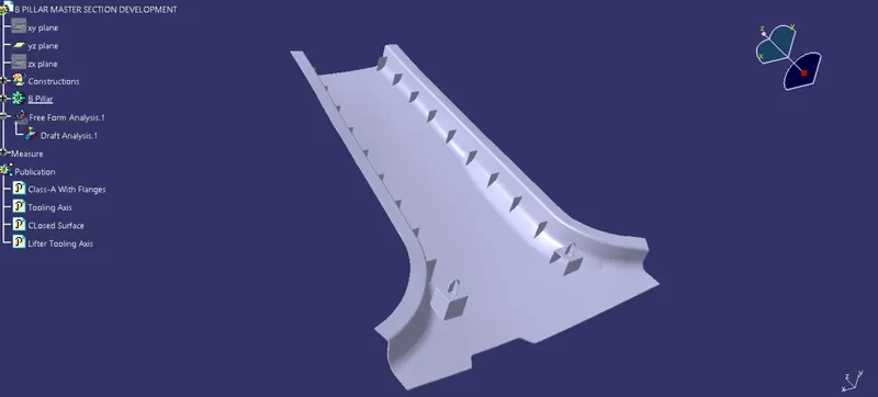
VII] Draft Analysis of Final Component:
Draft Analysis of Class-A Side:
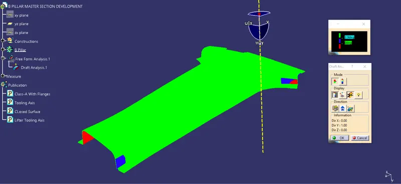
All the areas are with a minimum draft of 3 deg exept the patches shown in Blue.
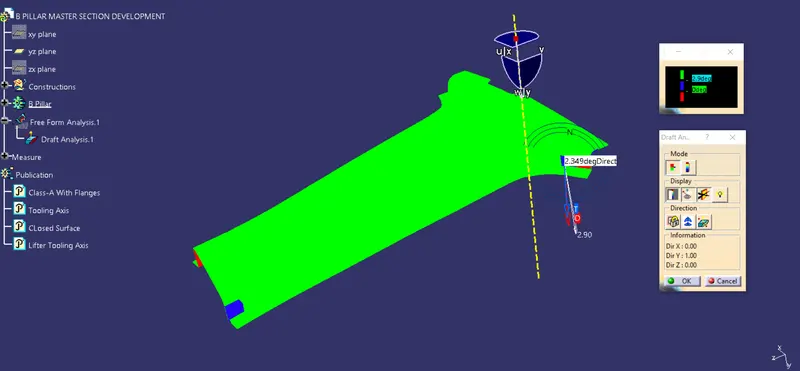
The minimum draft here is around 2.4 deg.
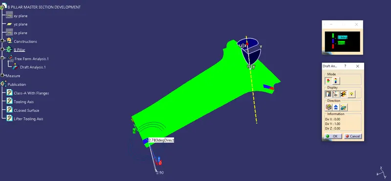
The minimum draft here is 2.7 deg
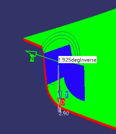
Draft Analysis of B Side:
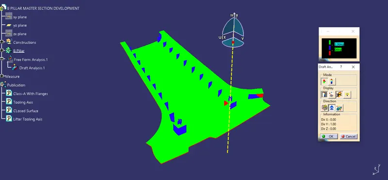
All the areas are with a minimum draft of 3 deg exept the patches shown in Blue below.
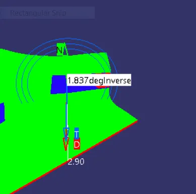
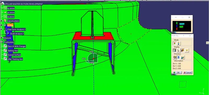
Draft Analysis of B-Side Features:
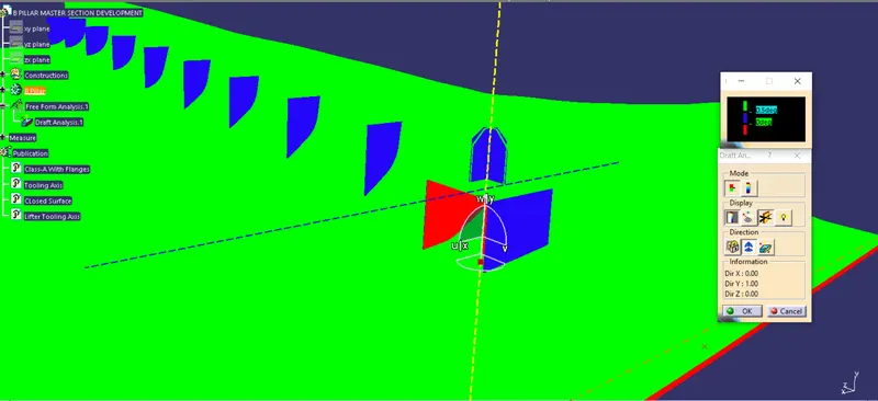
The minimum draft value here is 0.5 deg.
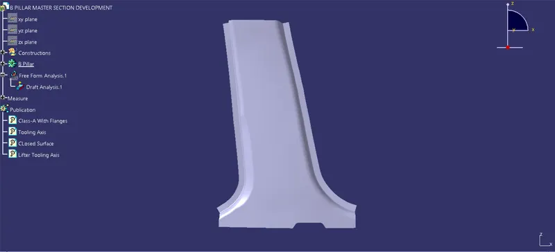
Completed Design:
Front View:
Bottom View:
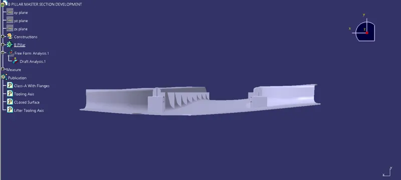
Side View:
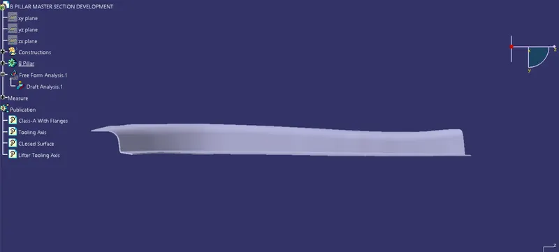
Isometric View:
Conclusion:
We have successfully designed the B-Pillar from the given Master Section.