Week 9 - Project - Master Section Development
Aim :
Door applique design with engineering features.
Objective:
- The tooling axis for the given Class-A Surface should be created to meet the requirements of the draft angle.
- Create the door applique plastic component through the given Class-A surface.
- Perform the Draft analysis on the model.
- Create the Heat Stakes and the locators considering the design rules mentioned in the video for the door applique.
Procedure :
1.Tooling axis for the class A surface :
- The model is opened and the class A surface is checked in all directions and the best direction is chosen that captures all the parts and features of the geometry.
Here the Y direction gives the proper view for the tooling axis.
- Now, we know the know Y direction is from where the tooling axis is going to lie but we don’t know the direction for the axis.
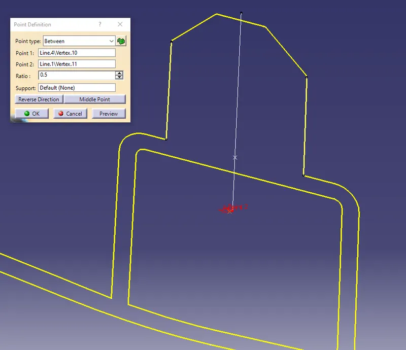
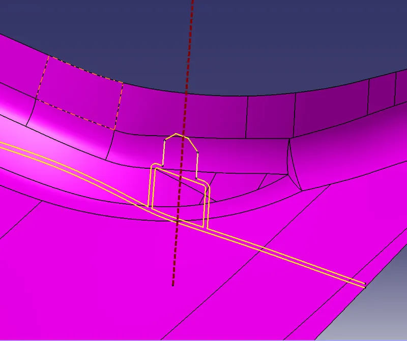
- So, the base is extracted and the point is created at the 0 coordinate (center of the surface) or a point in between two master section lines can also be used as a reference point for the tooling axis.
- Then at this point, a line or axis is created in the Y direction.
2.Performing the draft analysis :
Draft analysis is required to check if a part has the required draft or not. The draft is required so that a part can be ejected from its mould.
The Draft Analysis command enables you to detect if the part you drafted will be easily removed.
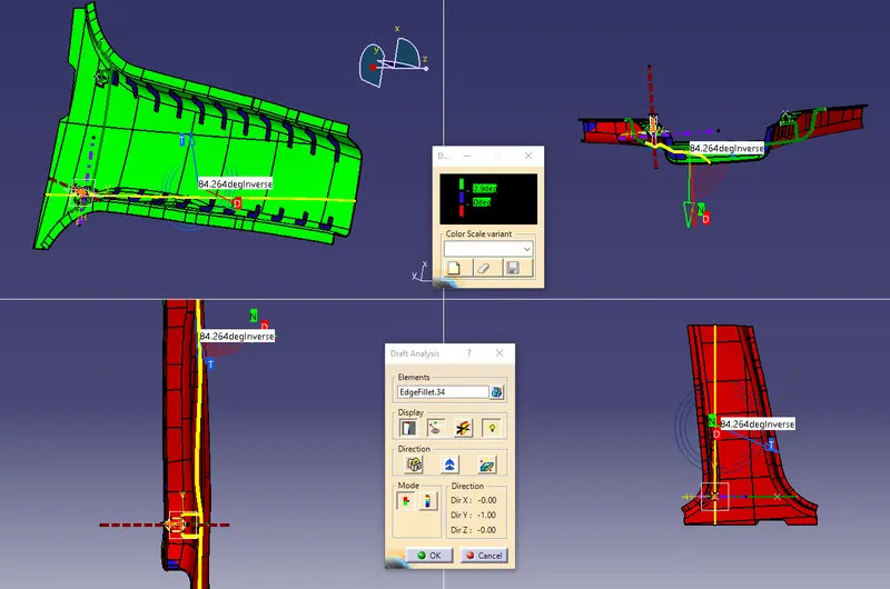
- To perform Draft Analysis, Go to the insert Menu >> Click Analysis >> Click Feature Draft Analysis option >> New Dialog boxes open.
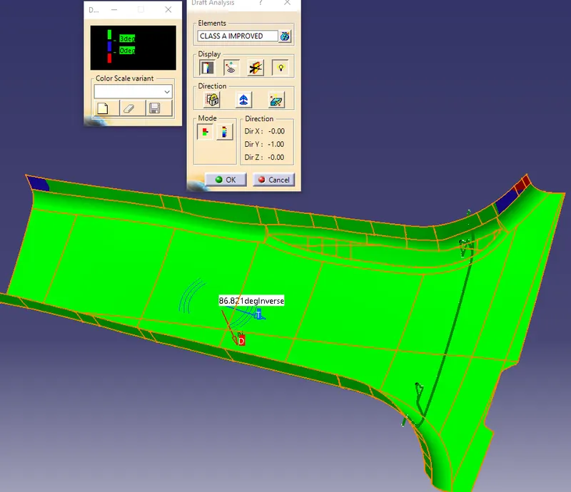
- Select the Elements as the Class A Model and the Direction as the Tooling Axis using the Compass option to define a new direction of the draft.
- Click OK to check if all the surface comes within the limits of 0 to 3 degrees.
- If the draft is more than 3 Degree then the surface will be shown as green.
3.Creation of B pillar cover surfaces:
a)B surface :
- The B surface is created from the A surface by offsetting it to the thickness value. Now, the thickness of the final component is 2mmso this obtained surface is offset below by 2mm.
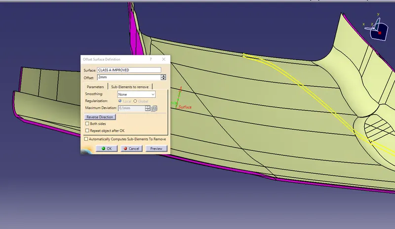
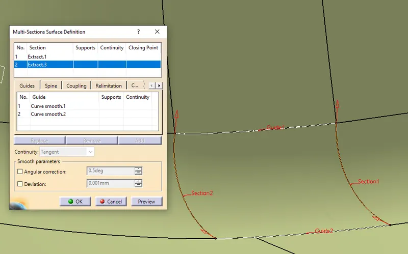
- The offset B surface has patches and missing surfaces that needed to be fixed up. For that, the multisection option is used by extracting the edges and then smoothing the guide.
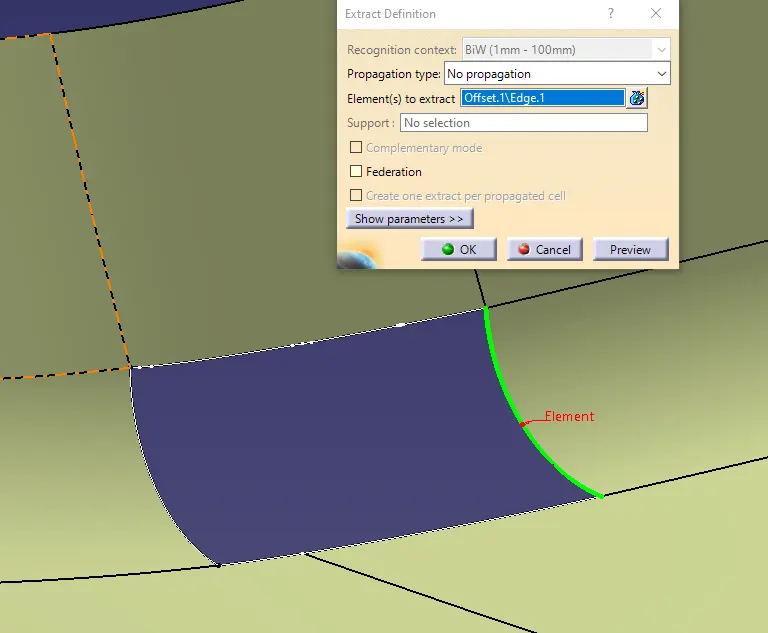
- Later the multisection is joined with the rest surface to avoid any gaps.
B surface with flange :
- The A surface does not have any flanges present at first but the master section of the B pillar shows a protruding flange for the final component.
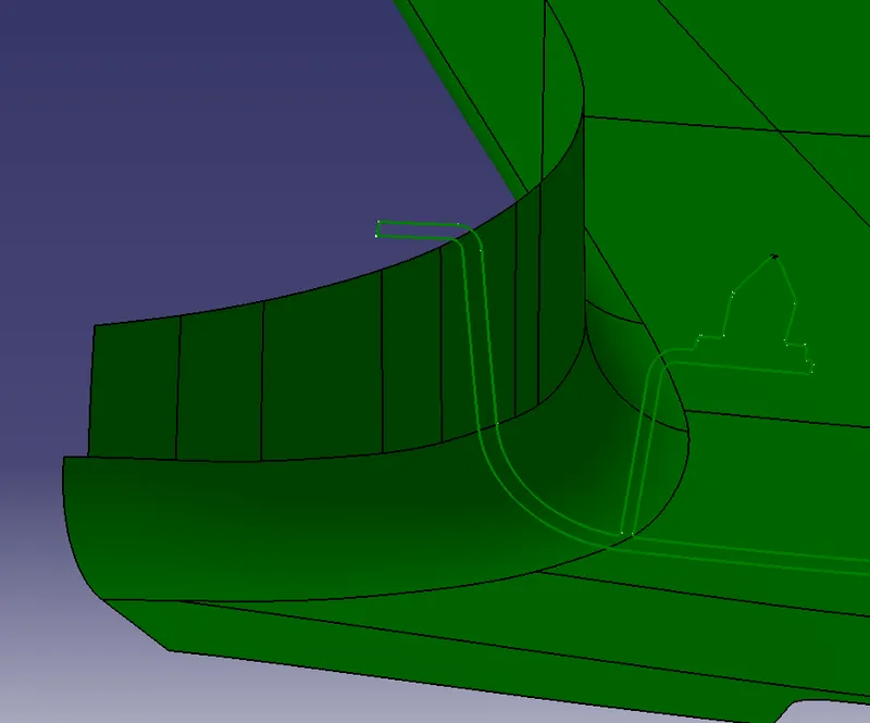
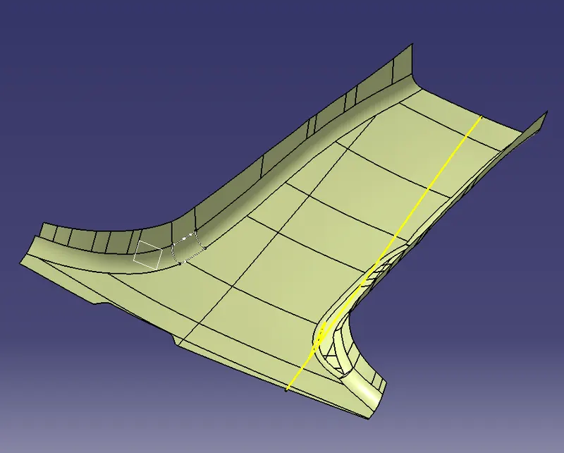
Master sections are the guides for design requirements that decide the component packaging after technical (Styling, Concept, or Class-A) surfaces.
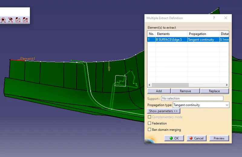
- So, the flange for both the A and B surfaces is created by extracting tangent continuity from the boundary edges for the B component.
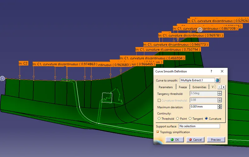
- Later the extracted lines are smooth to avoid any problems while sweeping.
- Then, the plane is created along the master section and the B surface intersected with these planes. The purpose of intersecting the surface is to have the reference of the sweep surface to match with the master section lines.
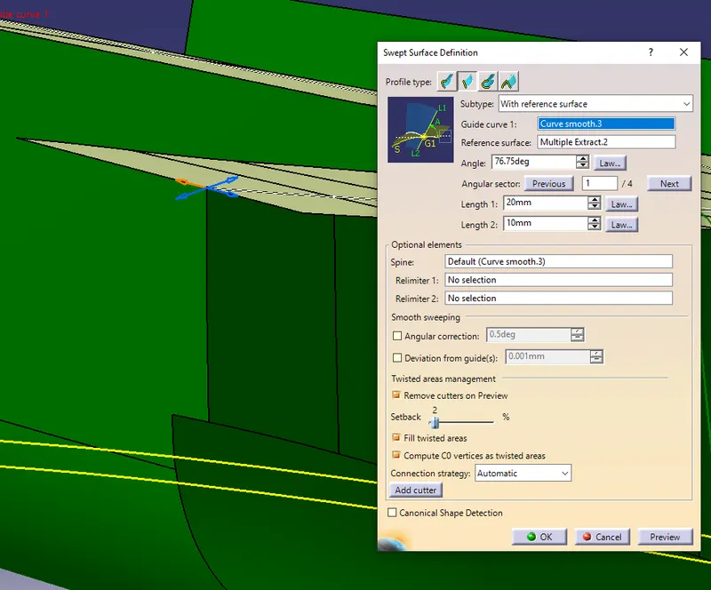
- Now, the boundary is swept with a reference surface until it is parallel or align with the B side of the master section.
- Later, this flange is trimmed to join with the B surface and the same can be done for other side and for the A surface also.
- In the end, edge fillets are provided by measuring from the master section.
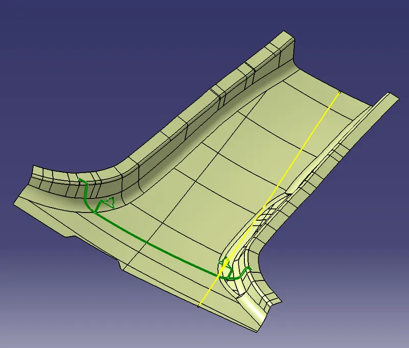
- C surface :
- After creating the B surface, the C surface needs to be created. To create the C surface, the sweep option is used along the draft direction.
- To create a sweep, there should be a boundary created to it. The boundary should be created separately as creating the boundary completely doesn’t create the sweep smoothly as the model contains the main unnecessary lines.
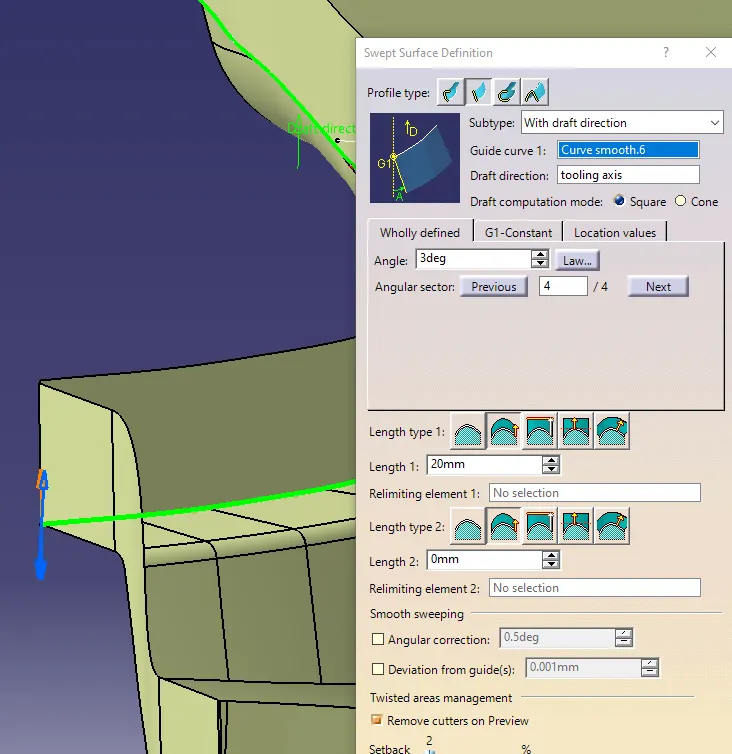
- To cover those, the smooth option is used to create the smooth surface and the Class A surface model is swept smoothly over the plane areas. Over the draft angled areas, the boundary should be created separately to create the sweep over that area
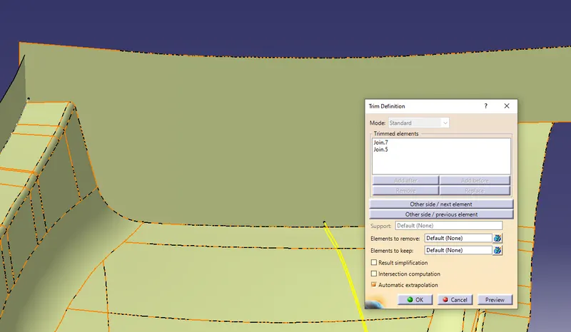
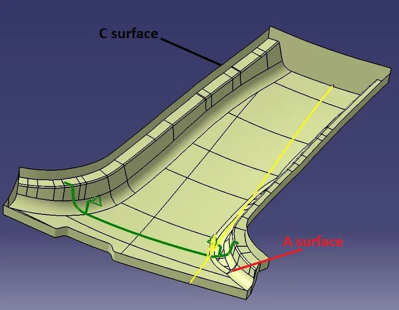
- Some regions are extracted followed by extruding and trimming with the A surface. By using the above series of tools the A and C surfaces are joined.
4.Final B pillar cover
- Now, start with joining the Class A and Class C surfaces together. Next, trim the combined surface with the Class B Surface to create the final surface.
- After creating the surface, go to the Part design option and create the solid using the closed surface option. The solid is created.
5.Dog house :
It is a ‘doghouse’ looking embossment for screws to attach one piece of plastic to another one. For example, you have a bumper cover, and you want to add a garnish to it. You would use doghouses to do so.
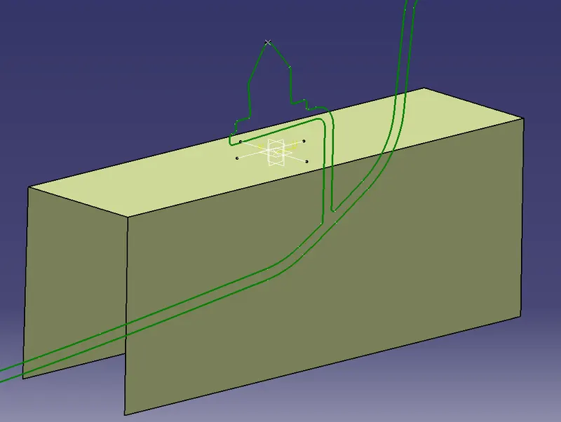
- The dog house is created on the base extracted and a C shape sketch is drawn for the dog house following the master section inner lines. This sketch is extruded for a certian length.
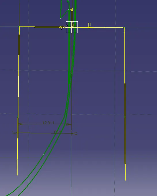
- Now, the other master section gives the closing surfaces for the dog house. So the lines are extracted, extrapolated, and then trimmed to get the surface for the dog house.
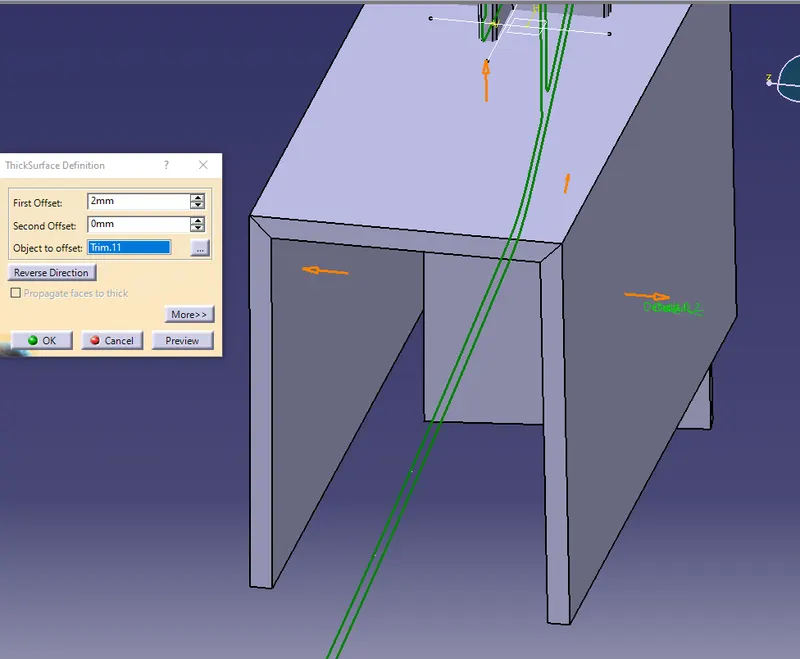
- The created surface is then thickened to outside for the thickness of 2 mm
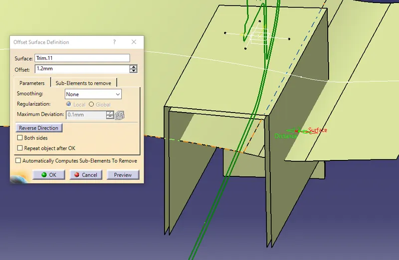
- For the lower part of the dog house, the inner walls of the box are extracted and offset by 1.2mm to the outer side in a shape generative workbench.
C= 0.4*2 = 0.8mm
- Then, the base A surface is intersected with the vertical back surface of the dog house to get the lines that will be cut out and this is profile can easily be covered with a side core or lifter axis.
- This profile is extruded and later trimmed with the offset surface to get the final lower cut out.
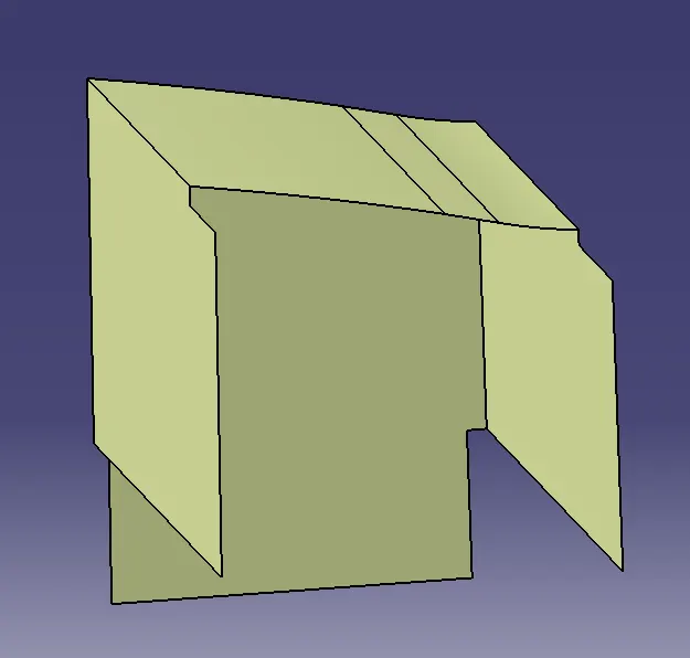
- Lastly, the cutout surface is split with the thickened dog house to obtain the final dog house.
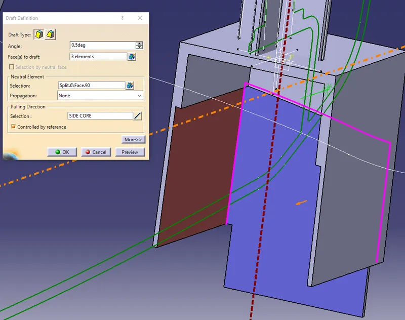
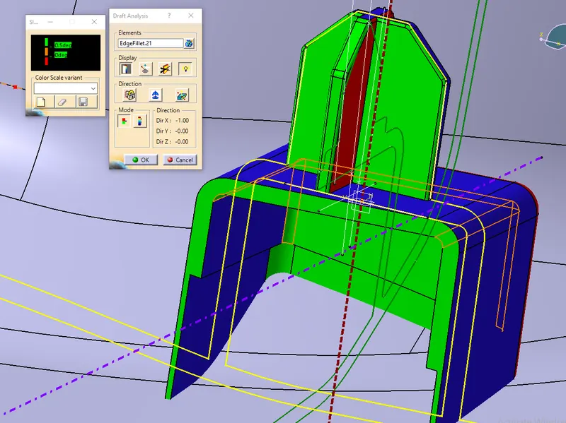
- Then, the fillets and draft angle of 0.5 is provided to the dog house. But the inside surface of the dog house is drafted in the direction of the side core tooling axis.
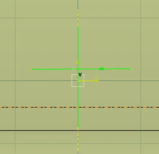
- 4-way locators
- To create 4 Way locators, the ribs should be created intersecting with each other.
- Open the Sketcher Workbench and Draw 2 lines intersecting each other and constraint it.
- Exit the Sketcher Workbench and Pad the Sketch with a thickness of 1 or 1.3mm
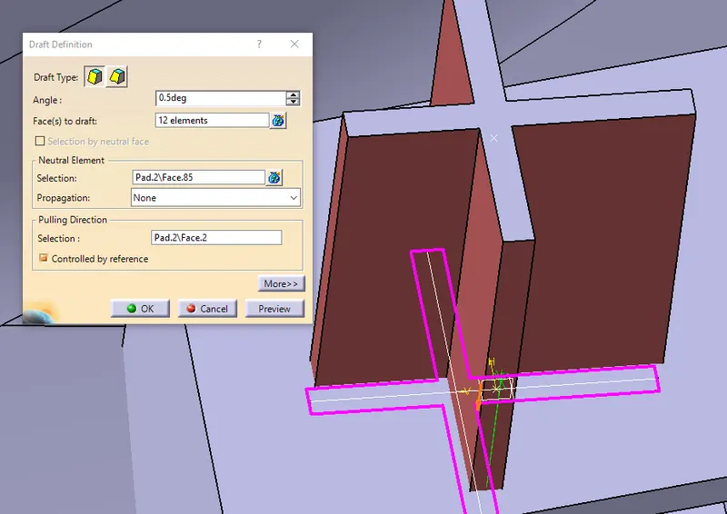
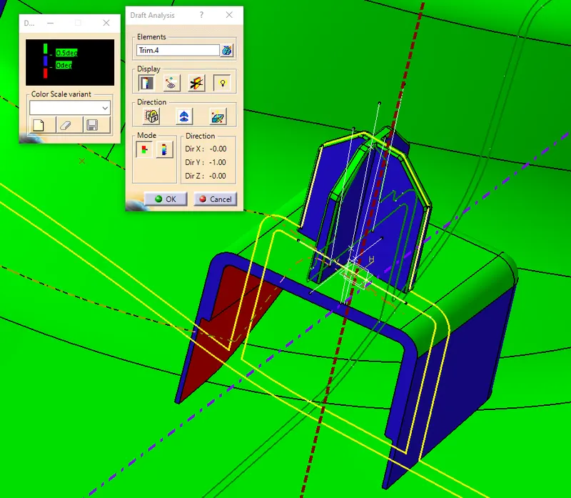
- Now, provide a draft of 0.5 degrees to the faces. Here the pulling direction is the tooling axis and the neutral face is the top face.
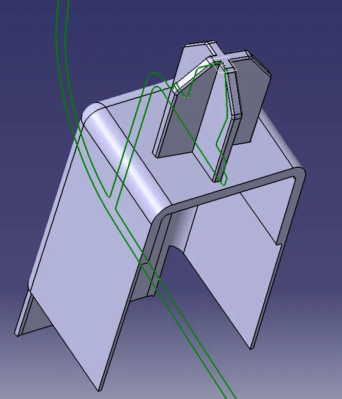
- Locate the locator above the dog house and Union trim the locator with the dog house and provide the chamfer of 5*45 to the edges of the locators and fillets of 0.3mm
The dog house is located to the other side by creating the plane in between two dog houses and performing the symmetry operation.
6.Creating the Ribs:
- To create the Ribs, Go to the Sketcher workbench and draw a straight line on the face you want to create a rib and constraint it.
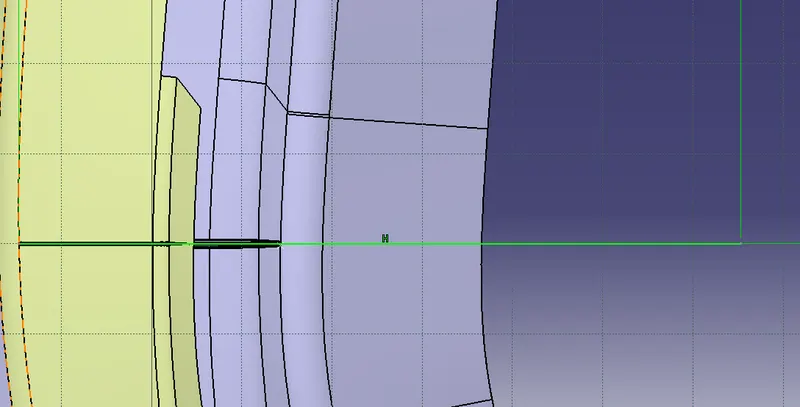
Extrude the line and then thickened the ribs.
- Go to the Class B or Class A Surface and select a line to extract. Select the Points repetition option to create the Points on the extracted line and give the offset distance as 50 and select the curve line.
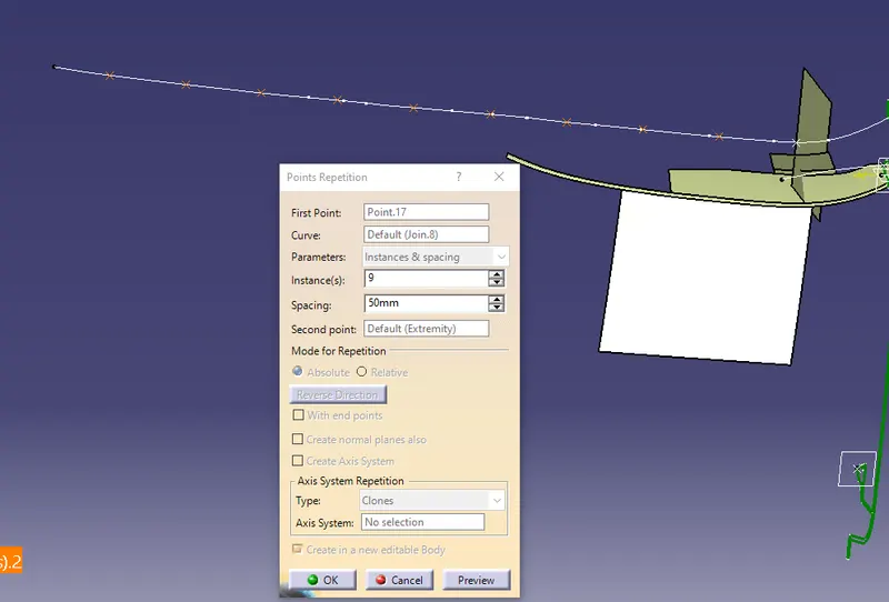
- Now copy the Part body and paste it on the main Tree Structure. Use the Translate option to move the copied rib part body from the starting point to the ending 50mm point.
- Offset the Class-B surface to 10mm and split it to cut the rib surface.
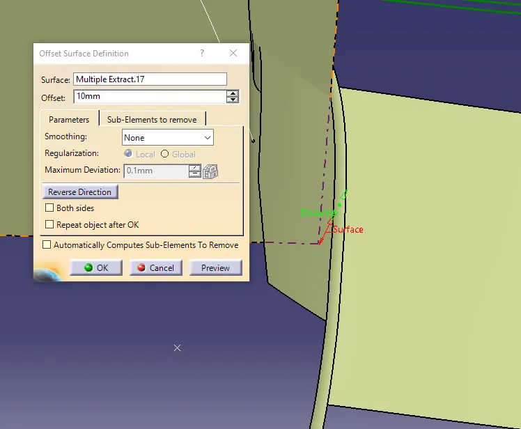
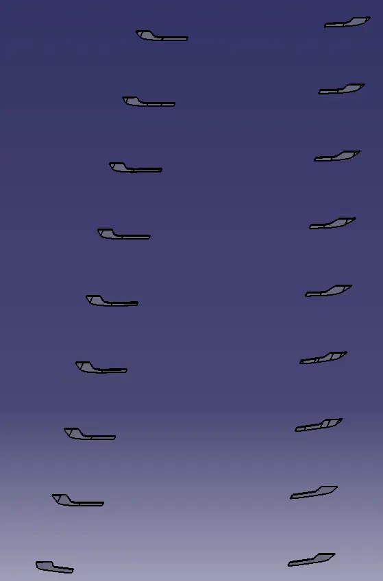
- Now, union trims the rib to get the final Rib structure by removing the unnecessary faces. Click Ok and Union trim the model. Follow the above steps repeatedly to create the ribs on both sides. The Final Solid component is created.
- In the end, provide the draft and fillets to the ribs of 0.1mm.
RESULTS:
SOLID CAD MODEL :
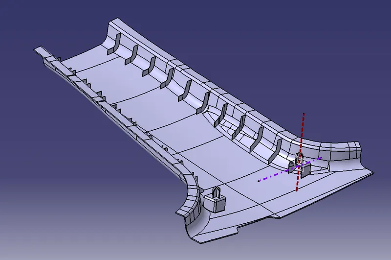
SURFACE CAD MODEL:
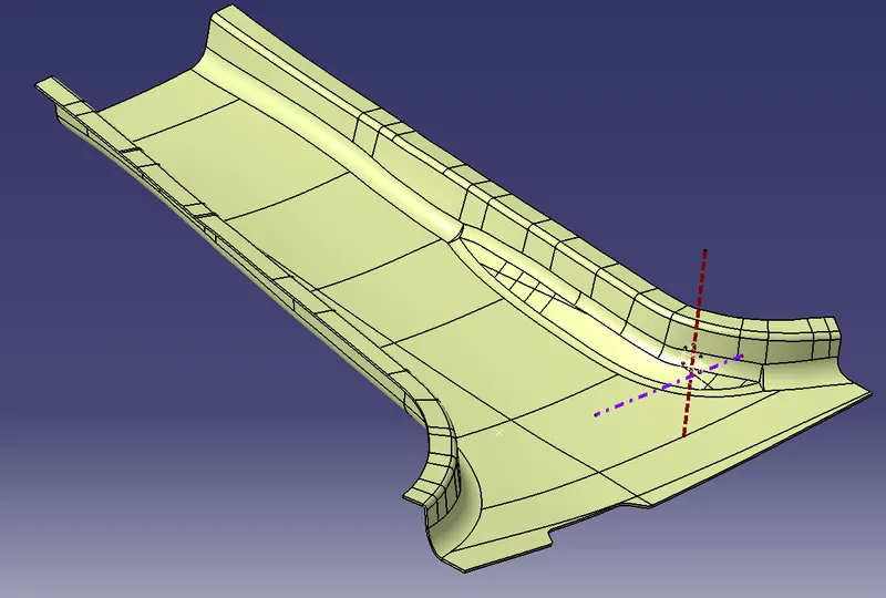
SIDE CORE TOOLING DRAFT ANALYSIS :
VERTICAL TOOLING AXIS :
FINAL DRAFT ANALYSIS :
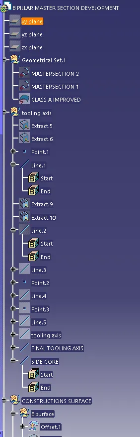
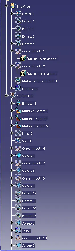
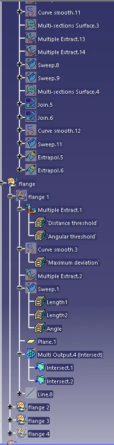
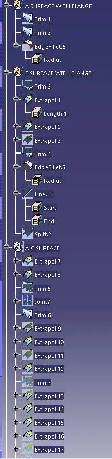
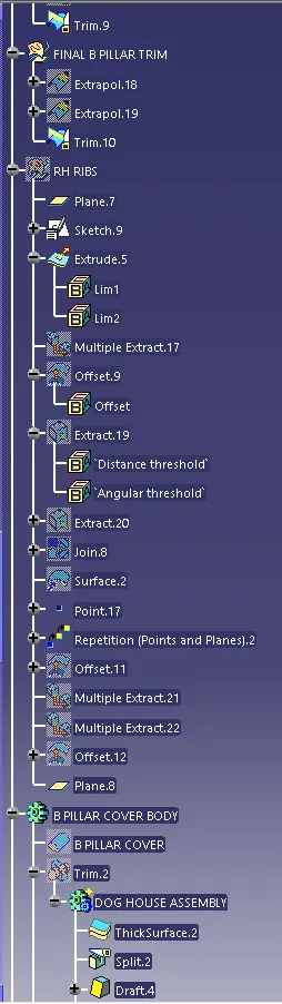
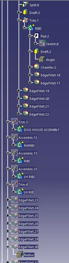
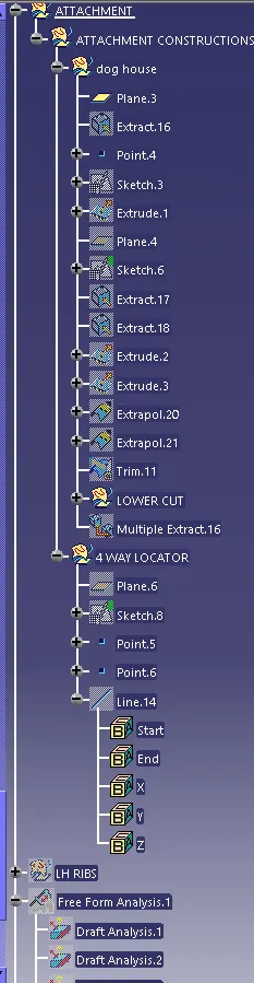
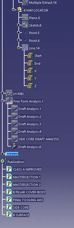
TREE STRUCTURE:
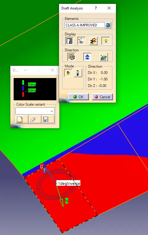
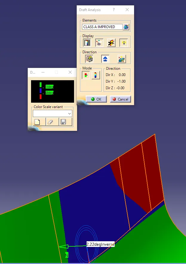
Here, the draft analysis for the final component was not satisfactory as some region special at the corners the draft value was around 2.2 and -1 degrees which means the current tooling axis wont be able to extract the component properly.
The solution can be to change the A class surface around that corner or to change the tooling direction maybe tilting to some angle so that it provides the positive draft angles .
But changing tooling direction means the master section also has to be changed which is again the long process.