Week 9 - Project - Master Section Development
B Pillar Creation using Master Section
Scope: To create tooling axis (main and lifter), closed body of a B Pillar from the given Class A surface, create B side engineering features and ribs using master section, and conduct draft analysis of the finished part.
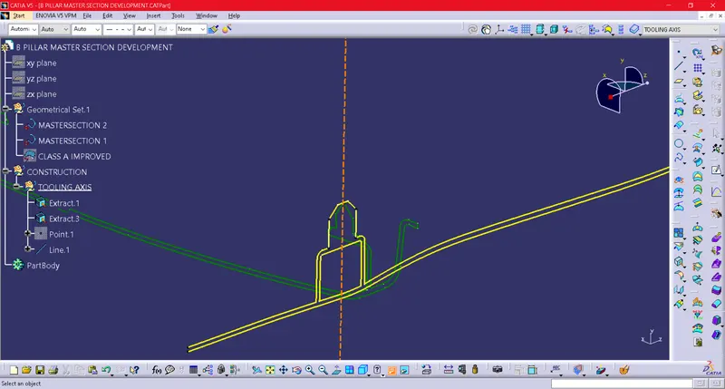
Tooling Axis: The first step is to check for ways to create a tooling axis which will clear most/all of the part in that tooling direction. Here we have chosen the master section geometry which is most likely to be perpendicular to the given Class A surface.
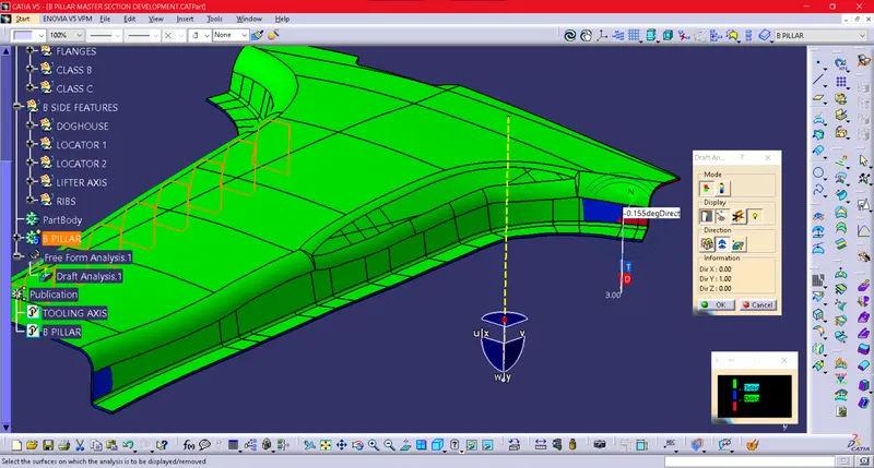
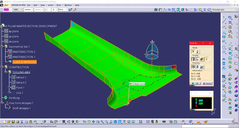
Once the tooling axis is created, it can be checked for draft by conducting the draft analysis tool. As you can see on the draft analysis, there are few patches where it does not clear the given draft limit of 3 degrees.
These areas can be seen with a blue/red colour patch. In the image below we have the draft analysis of the Class B side.
Closed Body creation with Flanges: After the draft analysis on the Class A surface, we move forward in creating the flanges onto the class A and B surfaces using the master section profile. We use the 'Extract' option to choose the two extremities (left/right) of the B Pillar Class A surface and use 'Sweep' with the extracted curve as the reference curve and the inner sides of the Class A surface edges to create a flange which matches the length and angle of master section flange.
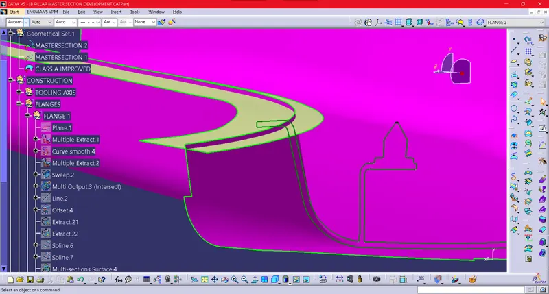
Once the flanges are created on both sides, we can offset them to 2mm as assumed to be the component's thickness. The offset is created for the Class B surface as well. Now for the Class C surface creation, we take the whole Class A surface as a curve using 'Boundary' option and use 'Sweep' to create the C Surface as shown below.
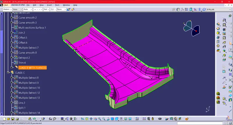
We make creation of Class A with flanges, Class B with flanges and a Class C surface with 3 degrees draft towards the outside so that the parting lines falls on the B side than the Class A side. The component is finally 'Trimmed' and is closed by using a 'Closed Surface' option from the Part Workbench.
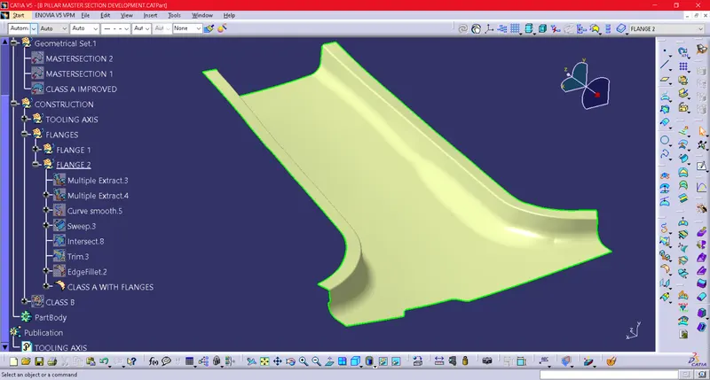
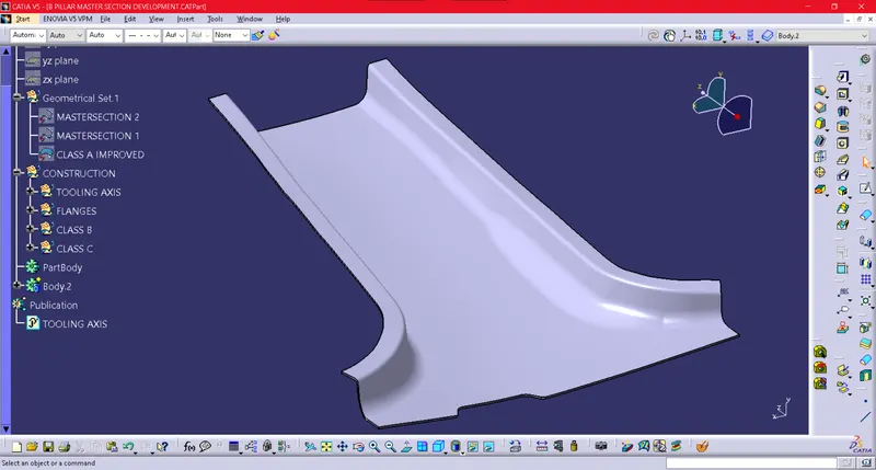
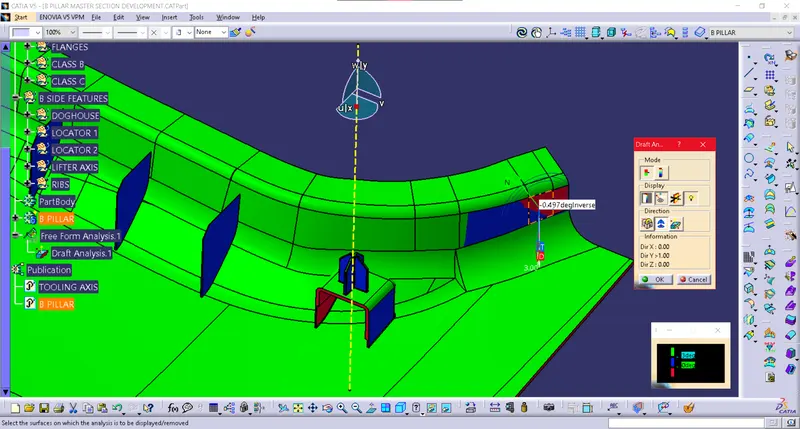
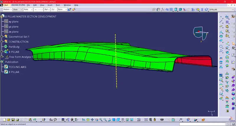
As the closed body is finished, it is important to check the Class C surface on the draft analysis and check for any abnormalities. Below is the Draft Analysis on my B Pillar closed body.
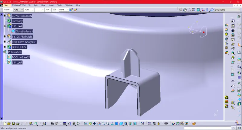
Doghouse and 4 Way Locator: By using the master section, the profile and limits of the doghouse can be projected onto the sketch and a subsequent doghouse is created by giving a thickness of 2mm, draft of 0.5 degrees with the main tooling axis, inside and outside fillets of 1mm and 3mm respectively.
The same method of projection of master section profile is used to create the 4 way locators on top of the doghouse. The design principles of plastic ribs is used for the locator faces. Finally the locator and doghouse are assembled with each other as seen below.
The assembly is then Union Trimmed with the main B Pillar component. The finished doghouse - locator assembly is to be checked with the main tooling axis for checking tooling feasibility of its outer surfaces.
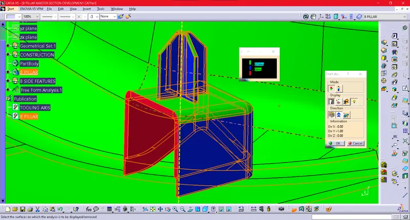
Once the outer surfaces are cleared with the main tooling axis, we then move to fix the inside surfaces using the lifter axis which is the axis perpendicular to the opening to the opening of the doghouse. But before that, we need to give the doghouse a cutout so that it avoid sinkmarkes on the opposite surface which is the Class A surface of concern.
The doghouse intersection part thickness is usually 40% of the main component thickness so in this case that would be 0.8mm and the height of the cutout on the doghouse is taken to be 5mm.
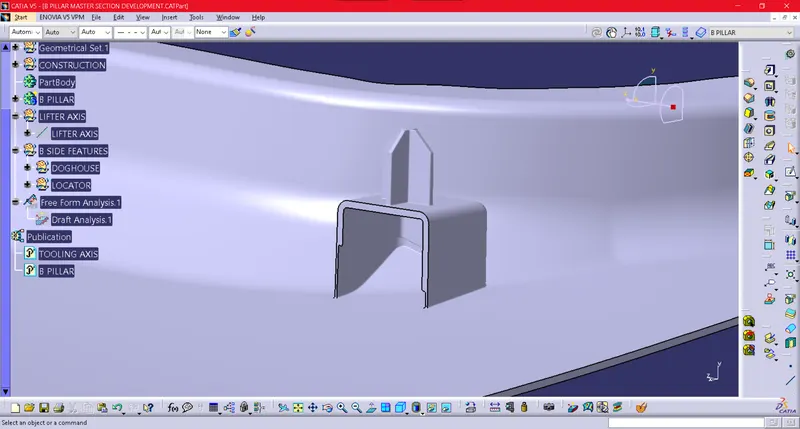
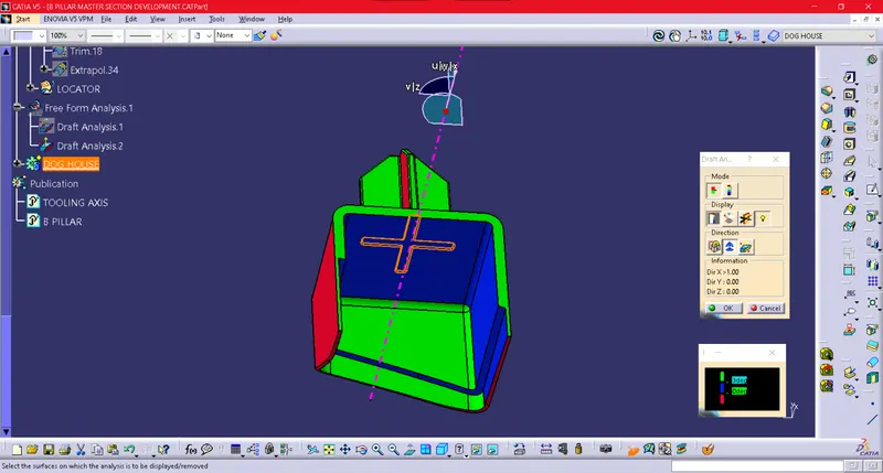
As we can see the doghouse internal features are cleared by the purple axis line which is the Lifter Axis in this case. The inner surfaces are given a draft of 0.5 degrees with the lifter direction.
The doghouse is finished by using a paste special with the result as a link and 'Translate' is used to move it in the other location using a midpoint plane between the two features obtained using extract.
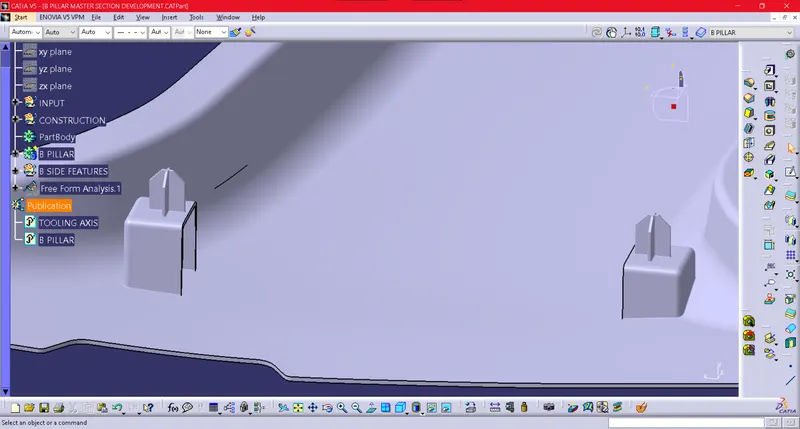
Power Copy: Now that the majority of the B side engineering features are finished, one major part of plastic components is strengthening using ribs at certain intervals. In this case, the design brief was given to create ribs at every 50mm intervals along the length of the component.
The individual rib features a draft of 0.5 degrees along the main tooling axis and a chamfer of 5mm. The distance of the rib from the side wall was kept proportional to the base area support between flanges.
One master rib is created on either side of flanges and then a 'Power Copy' is created as seen in the figure below. Power copy makes it easier to translate any feature along the component using input parameters for propagation, here we used the tooling axis and each line extract from the corresponding sketch of offset lines.
In the figure below, the ribs are 'Union Trim' with the B Pillar component and hence the long rib body is absent and the finished component is shown instead.
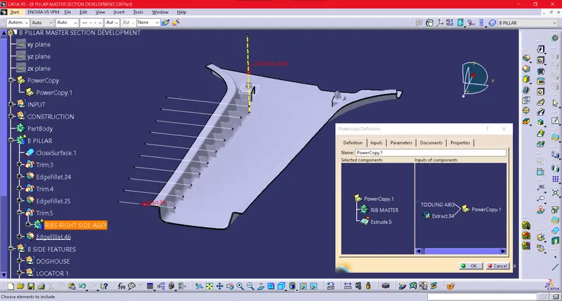
The individual rib geometry is shown below for reference, these values were assumed for convenience and keeping the material usage in mind. In case of specific load application along any point on the component, these rib geometry can be individually changed to meet the specific requirement.
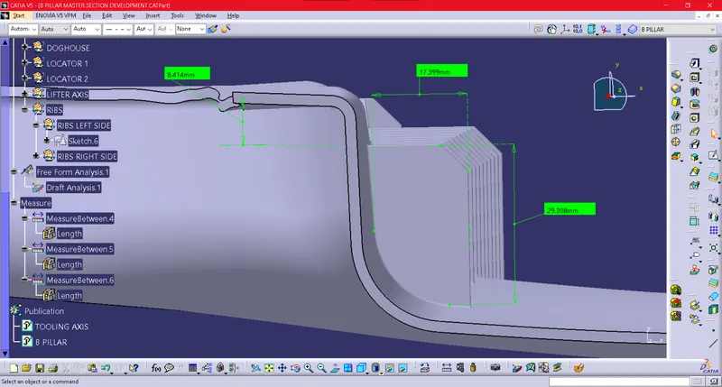
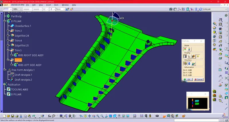
The Left and Right Rib Assembly is Union Trimmed with the B Pillar component and the below figure is how the final component looks. It is ready for a final draft analysis.
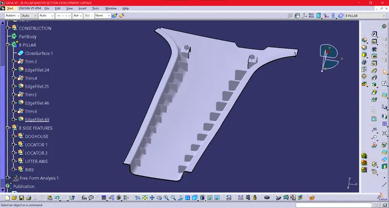
Draft Analysis: The final draft analysis is done to check for any indifference on the body as a last check to be done before approving the part and releasing the model for analysis and testing or mould making. Our draft analysis shows the component is almost cleared except the parts where it is red/blue patches, those areas needs modification of the Class A surface, Class B surface and the assembly or fixation elements.