Week 9 - Project 1 - Door Applique Design with Engineering Features
Door Applique Design with Engineering Features
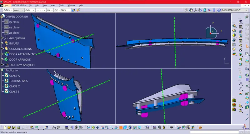
Scope: To create the Door Applique, perform draft analysis and create Locators & Heat Stakes on the B side for connection with the Door Attachment body.
Procedure: The Class A surface given was inconsistent with the fillet along the length of the body, so first, we reconstruct the Class A surface by extracting simple halves and later trimming them into an equal and consistent fillet value throughout the length.
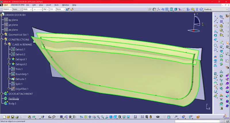
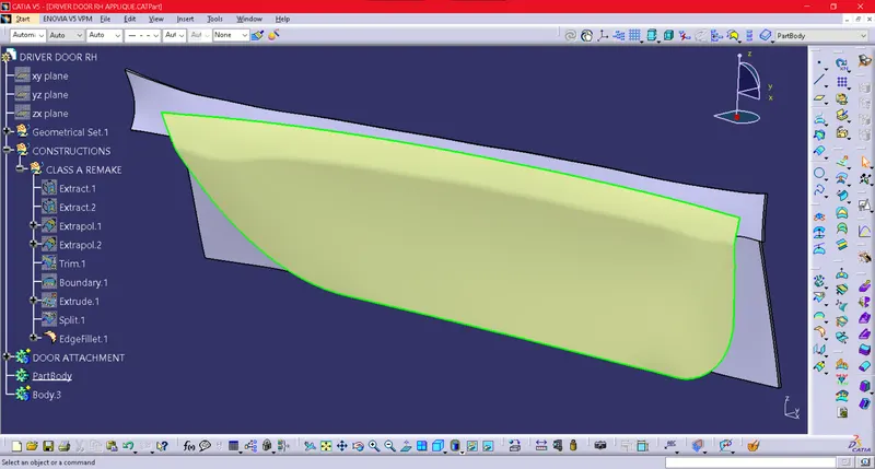
Tooling Axis creation: In order for the tooling axis to be at an angle equal with the curves along length and breadth, we intersect the above shown Class A with the XY and YZ plane. Below we have created bisecting lines for curvatures of each intersection profile.
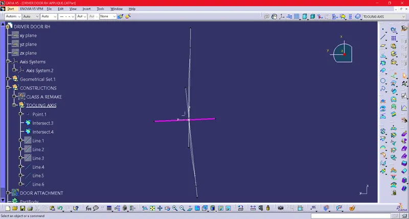
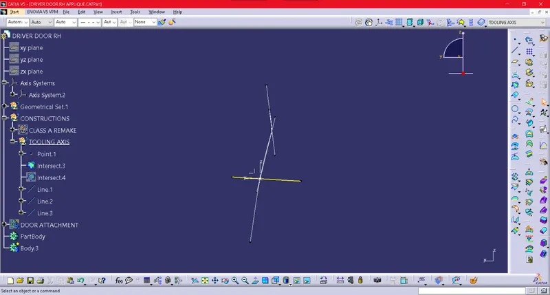
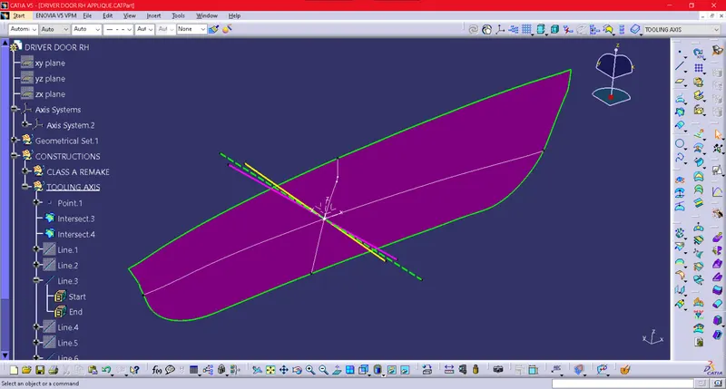
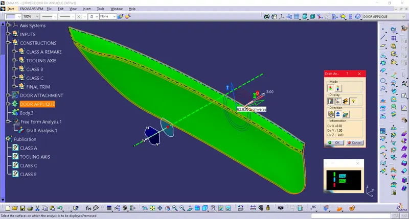
Draft Analysis: Once the main Tooling Axis (green dotted line) is created, we can perform the draft analysis. As expected there was no obstruction/congestion for the part as none of the surfaces were less than 80 degrees with the tooling axis.
Creation of Locators and Heat Stakes: Once we are through with the Tooling Axis and the Draft Analysis, we go ahead with the fixation technique and here we use the 3-2-1 Pin Principle where according to the length and width of a component we decide to create 4-way and 2-way locators at various positions spaced apart significantly.
These locators are given to arrest the translational and rotational degrees of freedom of the component to be attached. The general rules of chamfers, draft, and fillets of Ribs are applied here, and below are figures of well-defined 4-way and 2-way locators.
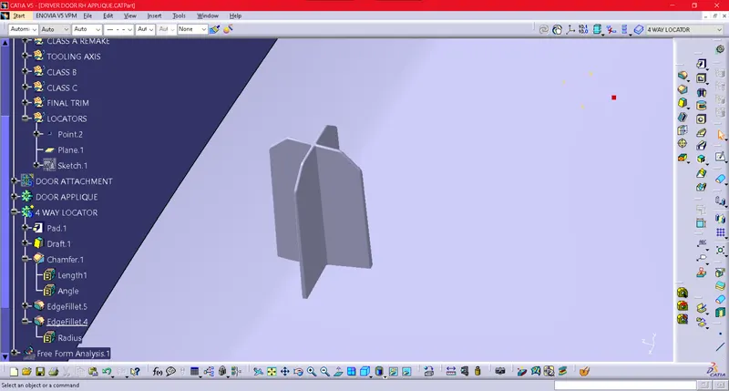
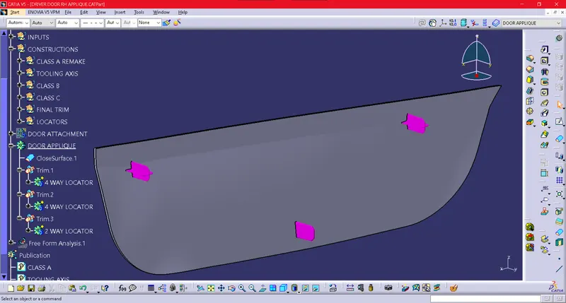
Then comes the positioning of Heat Stakes, we have extracted our Class A boundary and used the Parallel Curve to position the heat stakes location inside the component still far away from the locators. The height of Heat stakes should be lower than that of the locators as we want the locators to first make contact with the mating component.
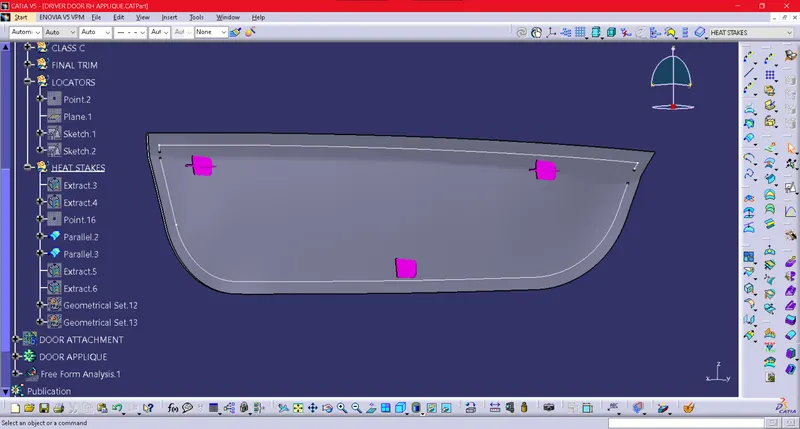
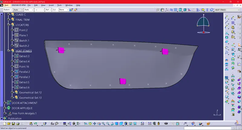
Here the positioning of heat stakes has been done based on the parallel curves used above, we can choose the number of heat stakes but it should not be excessive or too little.
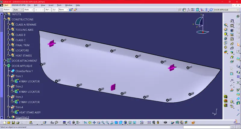
Once we have successfully created Locators and Heat Stakes, we should create the corresponding holes on the Door Attachment body as well. For the locator, a little clearance of 0.1mm should be given whereas, for the heat stake clearance holes, they can range between 0.25-0.5mm.
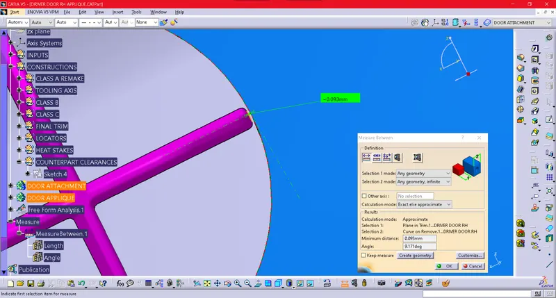
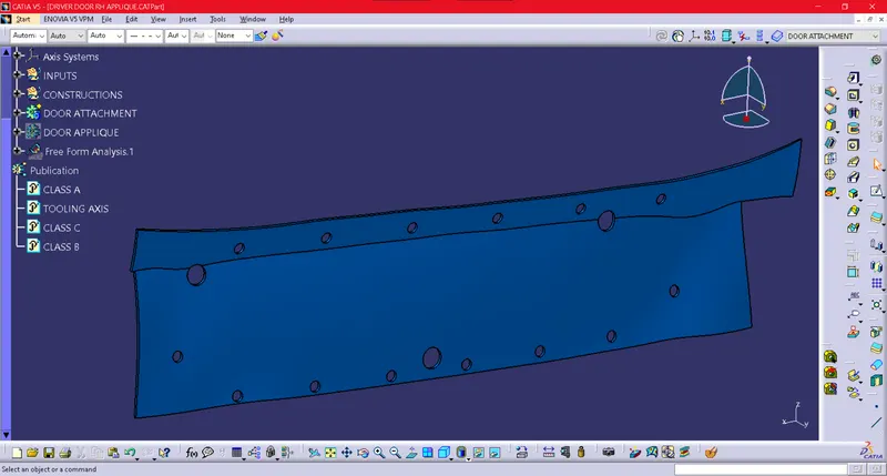
Conclusion: The final component with all fixation features and tooling axis in various views and orientations gives an idea of how the fixation can be made possible with minimum hassle and maximum productivity.