Week 9 - Project - A pillar Design with Master Section
AIM:
Create the Pillar, Plastic component through the given Class-A surface. To begin with, the tooling axis for the given Class-A Surface should be created meeting the requirements of the draft angle and at the end perform the Draft analysis on the model.
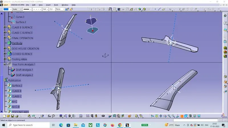
A below image is given class A with master section.
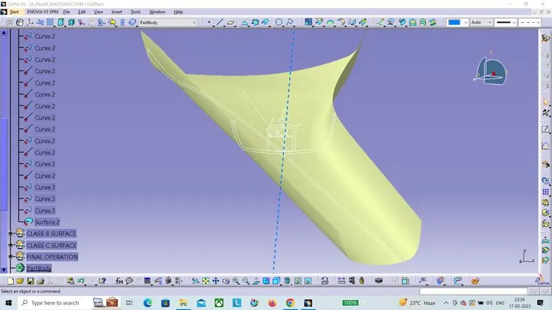
CLASS A SURFACE
Class-A (or 'Strak') is a term used in specifically in automotive design. It describes the final production Class data for the aesthetic parts of the car. The term 'Class A' is often misunderstood, but it's generally seen as the 'Holy Grail' of Class modeling.
- Since we copy the Class A from the original Class A, then create separate geometric set then paste it. Then join the Class A.
TOOLING AXIS CREATION
- Tooling axis is the axis through which the mold opens, it is the first step before the design starts.
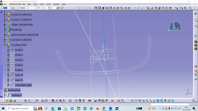
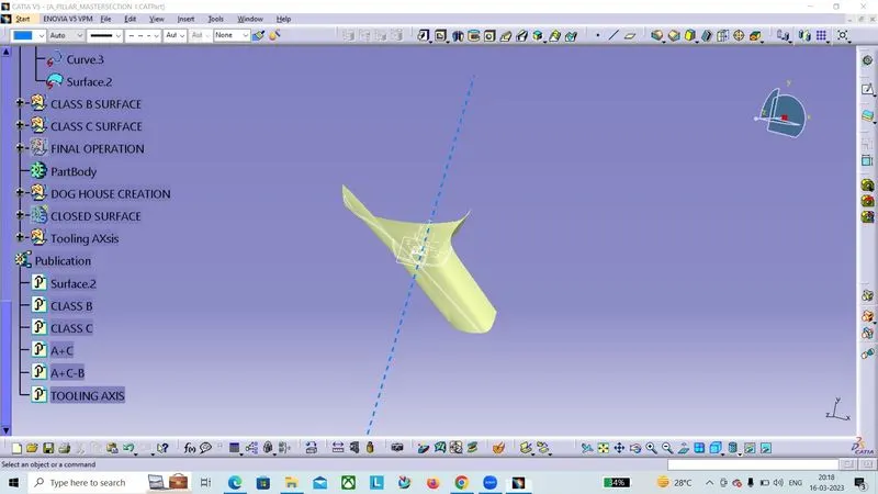
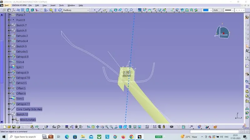
- In this project two tooling axis created one for the main part and other for the attachment feature dog house. The blue coloured tooling axis is the main tooling axis and pink coloured is the side core tooling axis.
- The main tooling axis is created by bisecting method , for the creation of tooling axis first two lines drawn through the master section by taking the vertex as reference through pont to point tool.
- After that a tooling axis is created by bisecting the two lines as shown in the fig below.
- The side core tooling axis created by taking a extract from the dog house and created a point in the middle of the extract and created a perpendicular line through that point.
DRAFT ANALYSIS
DRAFT ANALYSIS ON CLASS A SURFACE
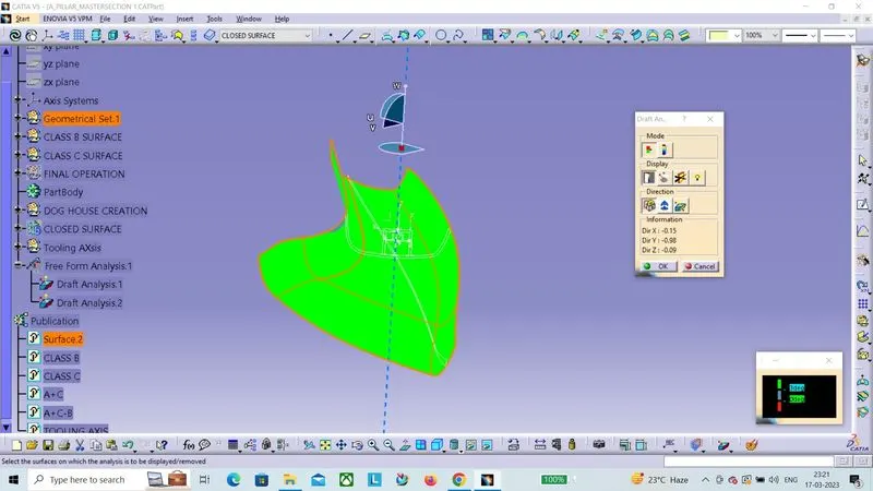
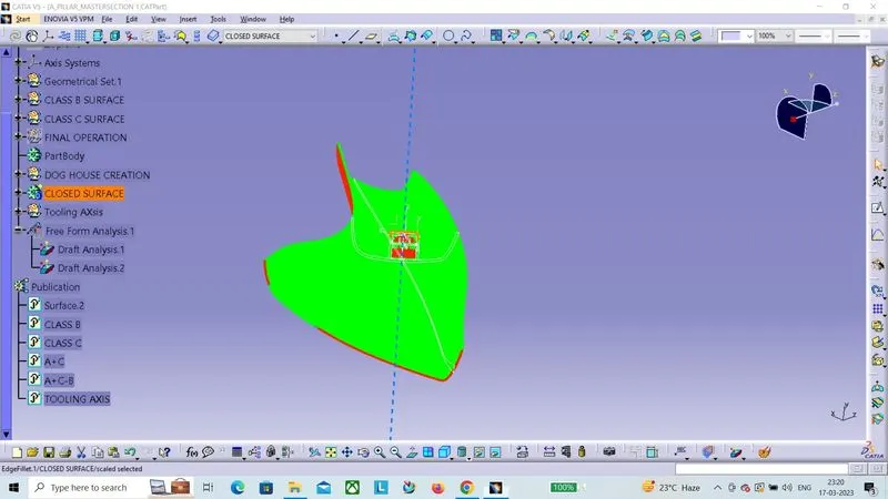
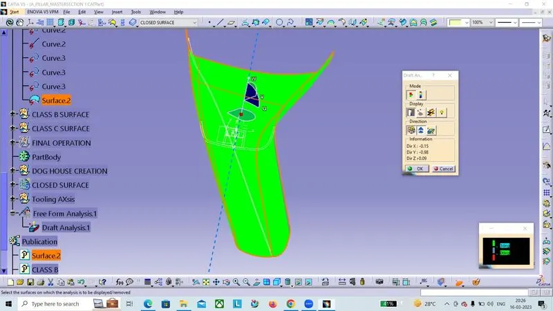
The draft analysis check is performed on the surface is to check wheather it satisfies the min draft angle as per the standards, the draft analysis on class A surface is doing before the creation of solid is to check whether the class A is drafted properly or not..The draft analysis is first done on the given class a surface with respect to the tooling axis , in that analysis the class A surface is cleared the min draft angle of 3 deg as shown below.
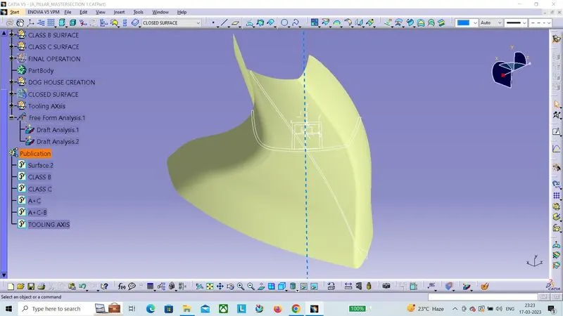
CLASS B SURFACE
- Now create a class B surface.
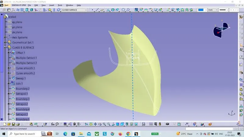
- In class B, first create base of class B from class A. Insert geometrical set define as class B, that is base of class B.
- Use extract command and extract a base from class A. Then use untrim tool get full body of a base. Next use extrapolate tool extended a base , then offset of 2.5 mm.
After Repair
CLASS C
- Class C is nothing but its connecting part of Class A & B.
- Unhide the class A and take boundary of its and now boundary select the all corner of a class A and use sweep commends the we get a class c of boundary in Class A.
- Then trim it finally get class C.
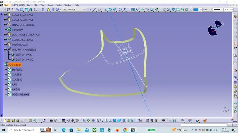
After Trim
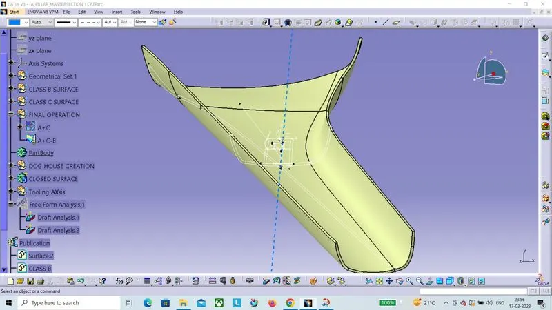
CLOSE BODY
- Go to the part body workbench then use close boby tool and finally get close body of base bracket
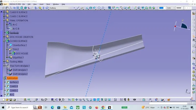
DOG HOUSE
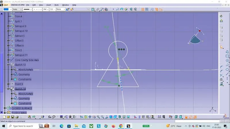
- Create sketch for a dog house, and pad it.
- Then pad this sketch, now shell the pad with 2.5 mm.
RIBS
- Now create a ribs is inside a dog house, create a sketch for a ribs,use master section.
- Then pad this sketch . Next use add with dog house, get a ribs for the body.
RESULTS
Finally used draft analysis tool, analysis model get positive results from a draft successfully Class A,B & C is required angles from a draft angle analysis. Analysis the draft angle red is below 0 degree and green is 0.45 dgeree.