Week 8 - Challenge 3 - Coin Holder Design
TO DESIGN A COIN HOLDER BY USING CLASS A SURFACE
AIM:
- To design a coin holder Plastic component through the given Class-A surface by creating a tooling axis and draft analysis of the given surface.
DESIGN PROCEDURE:
- To setup the class-A surface and to creating a tooling axis
- add draft angle
- To create a base surface of model
- To create a B-surface
- To create a C-surface
- To use close surface for creating a solid part model
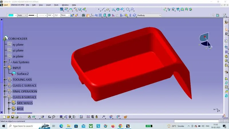
CLASS-A SURFACE:
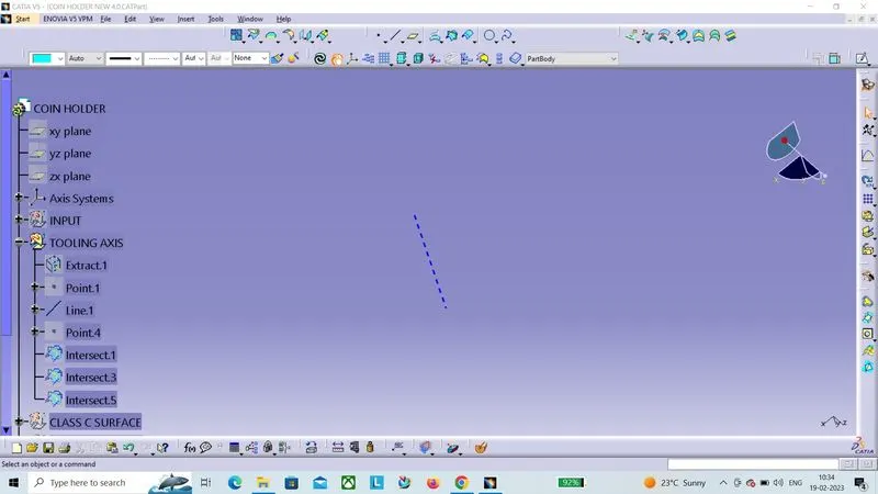
TOOLING AXIS:
- Tooling axis can be classified into two methods
- direct method
- For this model, to use a line at mid-point of the base of the coin holder
- Due to perpendicular walls of the class A surface
CREATING CLASS-B SURFACE:
SIDE WALLS:
- To create a side wall by extract the class A side faces
- To untrim the extracted side walls
- To extrapolate them for make sure to pass through all together for merge
- To trim the unwanted faces from walls by trim
- To offset the walls up to 2.5 m
BASE
- To create a base by extract the base from class A
- To untrim and extrapolate the base for final trim to create a B-surface
TOP WALLS:
- To create a top wall by Mutiple extract the class A side faces
- To extrapolate them for up to requirement
- To offset the walls up to 2.5 mm
OUTER FLANGE
- To create outer flange by Mutiple extract the class A outer flange
- To extrapolate them for up to requirement
- To create slider extract both part than extrapolate the sides using none istead point continuity.
- now join and than trim with outer flange.
CUTOUT
- To create a top wall by Mutiple extract the class A side faces
- To extrapolate them for up to requirement
- To offset the walls up to 2.5 mm
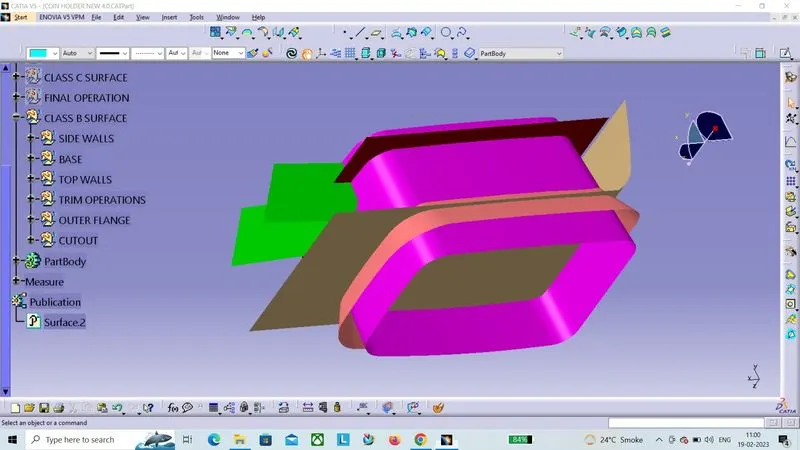
FINAL TRIM:
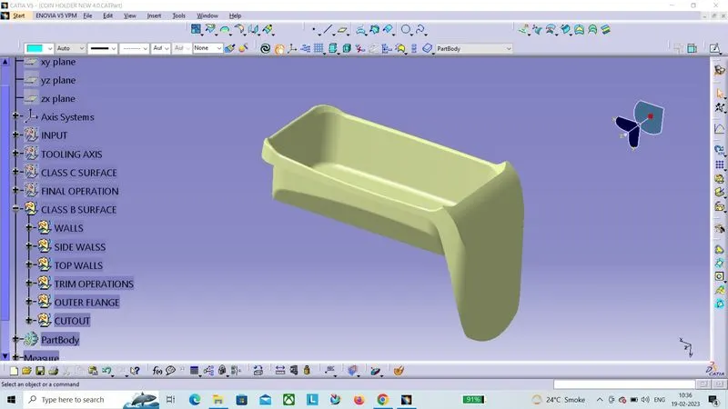
B-SURFACE:
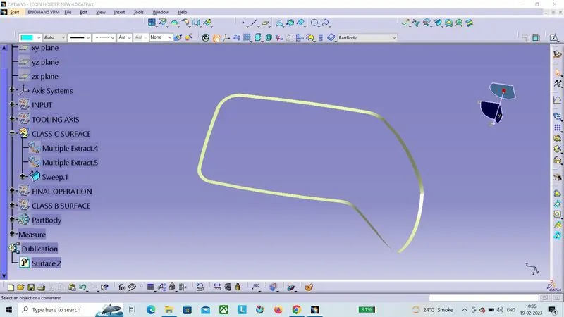
CREATING C- SURFACE:
- To use multiple extract tool on the class A surface
- The extract boundaries can be sweep at 90 degrees to the reference boundaries up to required length
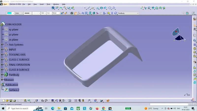
FINAL OPERATION
- The class A surface is checked for the connectivity of the surface and ensure it is completely joined and there will be no gap between the surfaces.
- If it is not join together make it with a minimum tolerance of 0.001 to 0.003 and check for connectivity of the surface.
- Connectivity of the surface can be done by two ways by join method and by boundary method.
- Than trim, Join and class B surface.
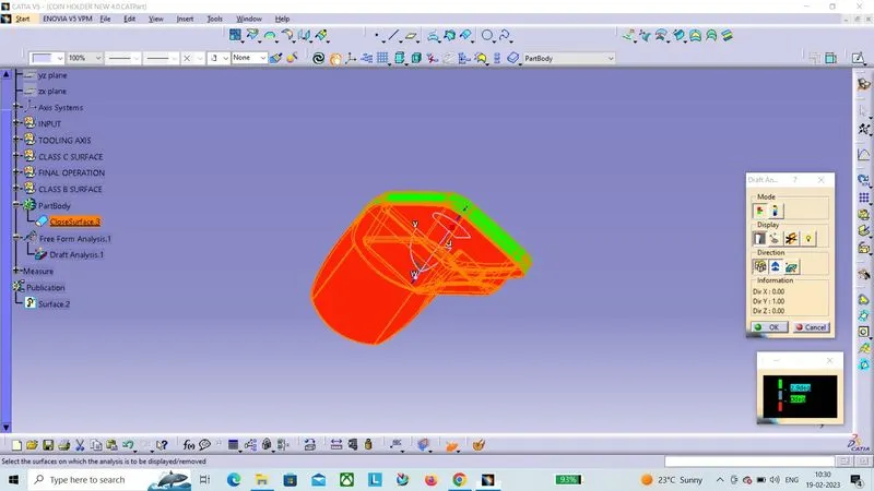
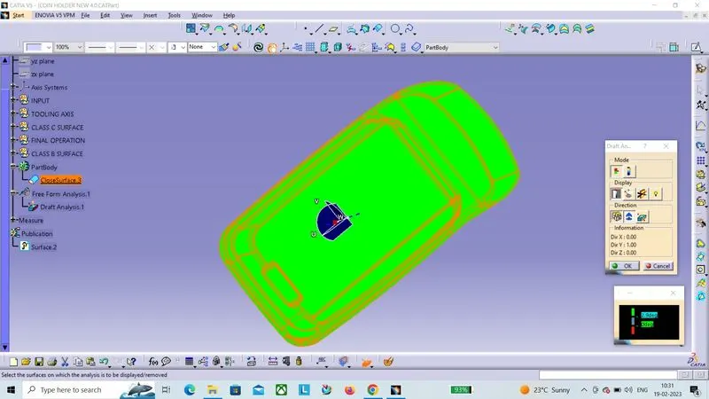
Draft analysis
- Draft allows for the component to release from the mould, most parts or applications require a minimum of 0.5 to 1 degree draft angle and 3 dgree draft angle is widely used as per the norm.
- Change the material mode to customize mode before moving to the draft analysis.
- Insert –analysis-feature draft analysis
- Defining the draft direction Select draft analysis from the tool bar and click on the compass symbol and pull the compass from the right side top corner of the workbench and place it on the component where want to do the draft analysis. ‘W’ of the compass and tooling axis should be aligned on the same line.
- Once the compass is aligned with the tooling axis click on the lock symbol and drag on the surface we will get a wrong mark then select that point a table will appear it shows the draft value on the table we can adjust the draft value and analysis it for all the edges and surfaces.
- By clicking the on the surface and using the flipping tool we can assign the Flipping direction, the color of the surface change as per the flipping direction .
- Analysis under running point and move the mouse on the surface and it will show the details of the surface deg direct at each and every point of the surface.