Week 8 - Challenge 5 - Door Trim Lower
DOOR TRIM LOWER
AIM: to make a model from the provided class-A surface.
INTRODUCTION:
CLASS-A SURFACE: a surface made by the designer which is given as input to the plastic modeler to work on. It is an aesthetic surface
and the outermost surface.
CLASS-B SURFACE: a surface below a certain thickness from the class-A surface is a class-B surface. This is the surface that contains
engineering aspects of a model.
CLASS-C SURFACE: a surface that joins class-A and class-B surfaces is a class-C surface.
METHODOLOGY:
In this model we have focused on the following things:
Tooling axis
Draft analysis
Class-B surface
Class-C surface
Making a solid model from the surface.
The following tools were used to reach the final step:
Extract
Un-trim
Trim
Extrapolate
Offset
Edge fillet
Boundary
Sweep
Join
Close (part design)
METHOD TO CREATE THE MAIN TOOLING AXIS:
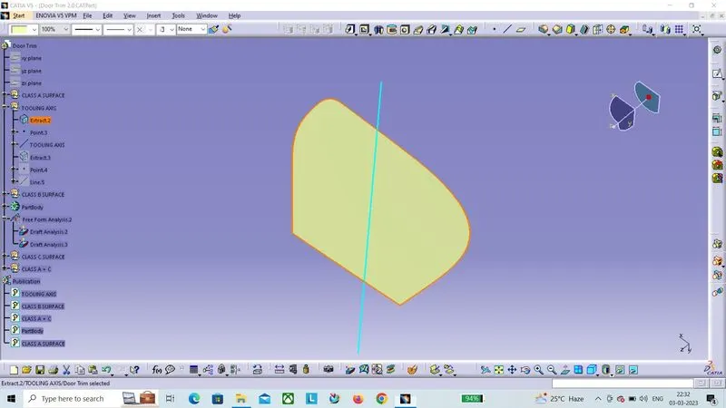
Now, to create our Main Tooling Axis using the first method, we'll choose a vertex as shown in the image below to create a line using the 'Line-Definition' command while choosing our Line-Type as 'Normal to Surface' where our direction will be towards the X-Axis.
DRAFT ANALYSIS FOR THE CLASS A SURFACE USING THE MAIN TOOLING AXIS FROM THE FIRST METHOD:
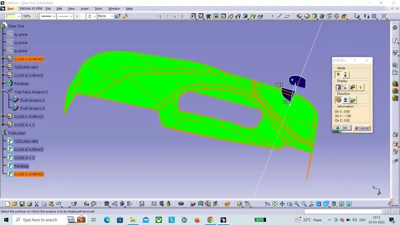
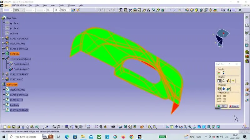
Now, We will perform a Draft Analysis on the Class A Surface itself using the Main Tooling Axis created using the First Method:
Before starting with a Draft Analysis Operation, we will go to the 'Customize View Parameters' option under the 'View Toolbar'. Then we will enter the 'Customize View Mode' where we will go under the 'Mesh' option and select 'Material' and press 'OK'.
To start the Draft Analysis in the 'Generative Surface Design Workbench', we will go to 'Insert' and then look for the option called 'Analysis'. Once found, we will go under that and click on 'Feature Draft Analysis. This will open the 'Draft Analysis' Dialogue box. There, we will ensure that under 'Mode' we have selected 'Quick Analysis', under 'Display' we will select 'Show or Hide the Color Scale' and then select '3 Degrees' as the permissible draft angle. Then, under 'Direction' we will choose the icon with the symbol of the compass on it which stands for 'Use the Compass to define the new current draft direction'.
PROCEDURE TO CREATE THE CLASS B SURFACE:
We'll start the procedure by creating an offset for the entire Class A Surface at a distance of 2.5mm as that is the desired thickness for our final plastic component.
As this is a complex surface hence the offset will fail to offset every element according to our necessity. It'll select some sub-elements that belong to the filleted regions by themselves that we have to remove to get the rest of the surface that is offsetted.
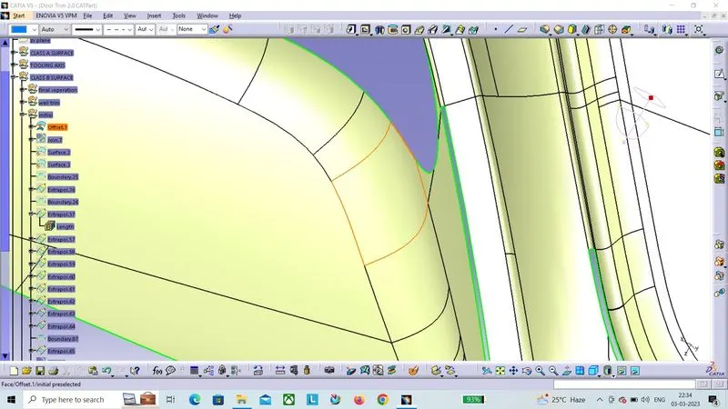
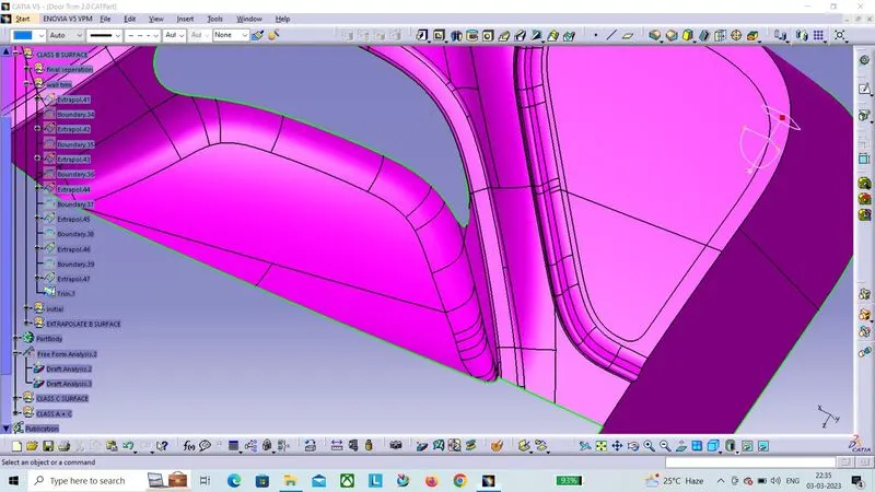
These 'Sub-Elements' will get selected by themselves to be removed if we want to obtain the rest of the offsetted surface.
TRIM OPERATIONS:
First, we'll perform the trim operation between the FIRST and SECOND regions.
After that, we'll trim Use Multisection to fill the second uncoversed surface by using "join" ccommond with subelement to remove.
Last surface we also first use "join" command and select the surface which you want to remove in "subelement to remove"
to fill the surface use multi-section command.
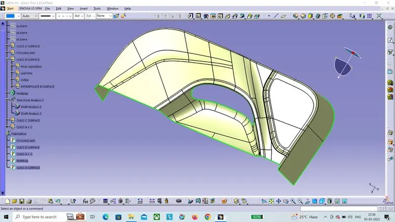
Final operation is to trim with walls and apply edge fillet and we get the result as shown in fig.
PROCEDURE TO CREATE THE CLASS C SURFACE:
We'll create the Class C Surface with respect to the Class A Surface and provide draft angles to those surfaces that are parallel to the Main Tooling Axis. Surfaces at the bottom won't be needing any draft angle as they'll get cleared by the core itself. To create the Class C Surface we have to use various commands such as Sweep with Reference Surface and With Draft-Direction depending upon the necessity and at places where it'll be difficult for us to create a surface using Sweep, we'll use Multi-Sections Surface to create those surfaces.
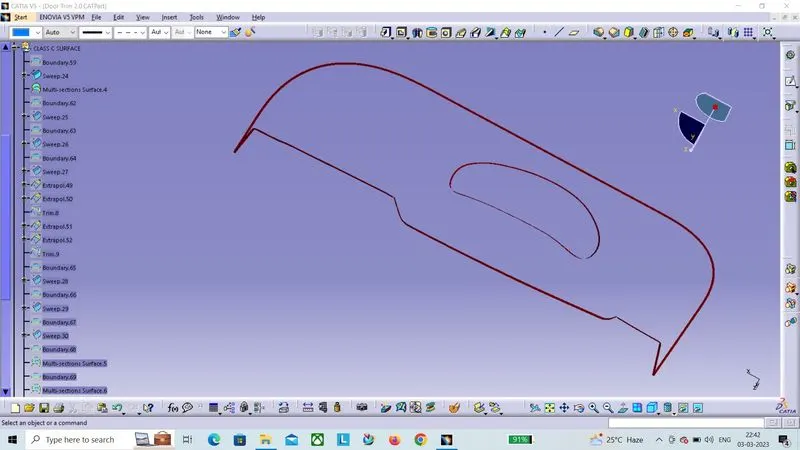
We've to create two Class C Surfaces, one is for the outer surfaces and the other is for the holed region inside the component and both of them are shown below:
Inner Class C Surface and Outer Class C Surface:
FOR FINAL MODEL
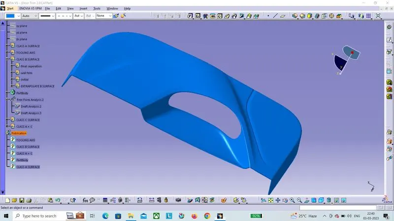
Join class-A and class-C surfaces together.
Then Trim the class-B surfaces to them.
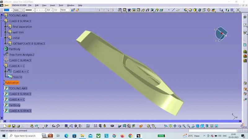
Go to the part design and close the feature.
Run draft analysis on the model.