Week 9 - Project - A pillar Design with Master Section
AIM :- To design A -PILLAR , from the given input mastersection and CLASS A surface.
OBJECTIVE
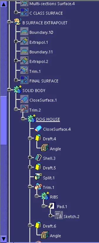
The main objective of the project is to create a solid body from the given class A surface and the master sections, and performs draft analysis in the various stage of design.
TOOLING AXIS CREATION
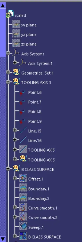
- Tooling axis is the axis through which the mold opens, it is the first step before the design starts.
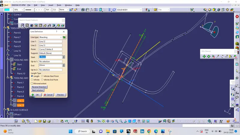
- In this project two tooling axis created one for the main part and other for the attachment feature dog house. The blue coloured tooling axis is the main tooling axis and pink coloured is the side core tooling axis.
- The main tooling axis is created by bisecting method , for the creation of tooling axis first two lines drawn through the master section by taking the vertex as reference through pont to point tool.
- After that a tooling axis is created by bisecting the two lines as shown in the fig below.
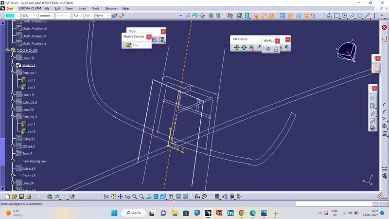
- The side core tooling axis created by taking a extract from the dog house and created a point in the middle of the extract and created a perpendicular line through that point.
CLASS B SURFACE:
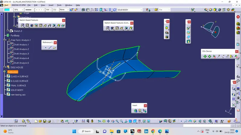
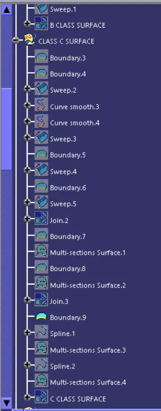
To create the class B surface, offset the class A surface inside as per our thickness requirement (here the thickness is 2.5mm, so I offset the class A to 2.5mm inside). Once the offset is created, we can observe some patches on the offset surface by taking the boundary for the offset surface, those patches are formed due to the fillets on the class A surface. We need to cover those patches with the help of the multi-section surfaces command by extracting the patch boundaries. Once all the patches on the offset are covered properly join all the patches with the offset surface, to get the replicated surface of the class A surface.
CLASS C SURFACE:
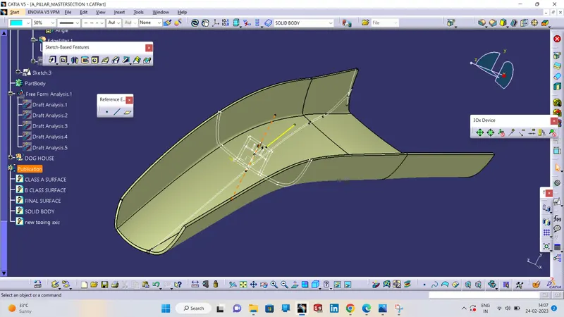
I used the sweep command to create the class C surface concerning the boundary of the class A surface. Initially, I extracted the boundary of the class A surface with tangent continuity, and I sweep the extracted boundary concerning the surface at 93deg (for draft angle) for 4mm to intersect properly with the class B surface. Once we sweep all the surface boundaries of class A, extrapolate the sweeped surfaces until both surfaces got intersect properly, and trim them to remove extended extrapolated surfaces to get a proper sweep boundary throughout the entire surface, including the centre hole of the door trim. Now, join both class A and sweep boundary to get the complete class C surface.
SKETCH OF DOGHOUSE
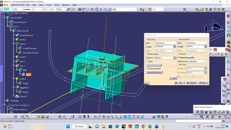
CREATING RIBS;
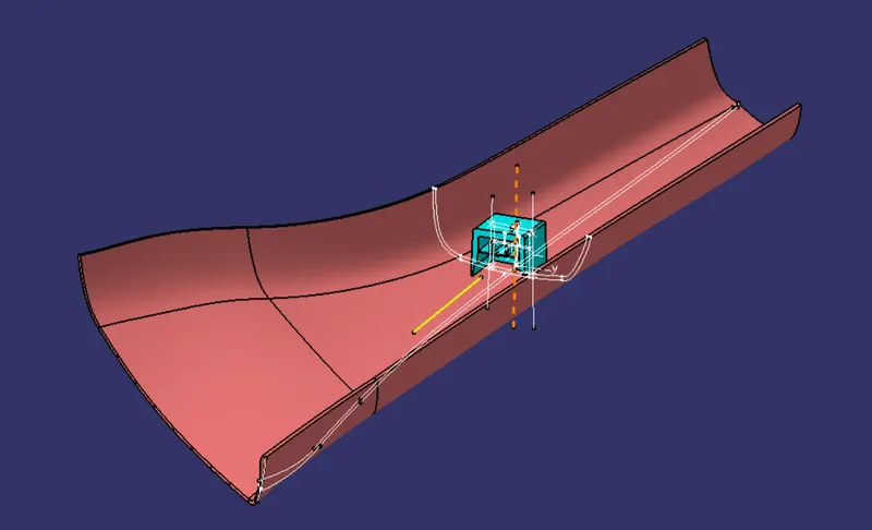
ISOMETRIC VIEW
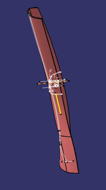
FRONT VIEW
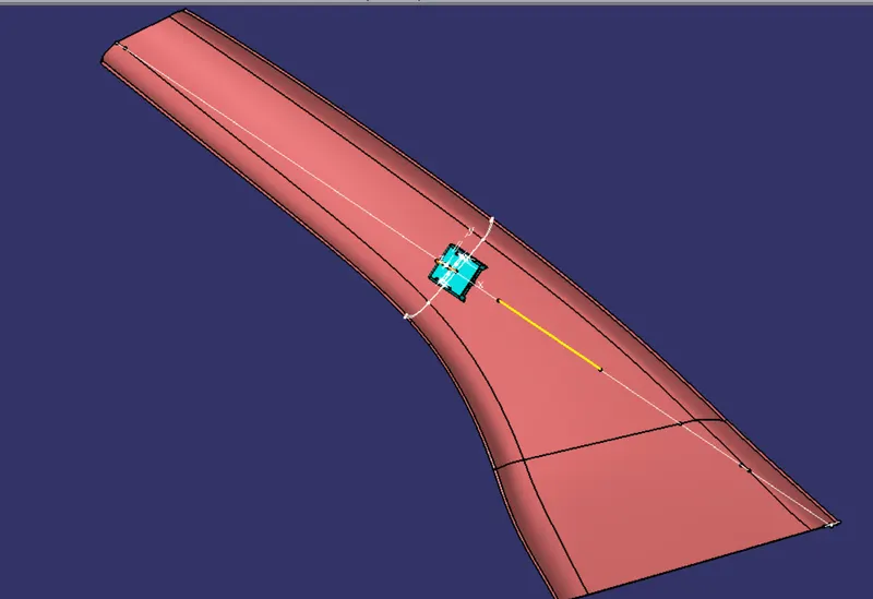
SAID VIEW
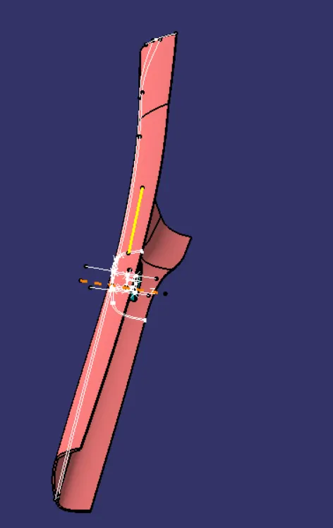
TOP VIEW
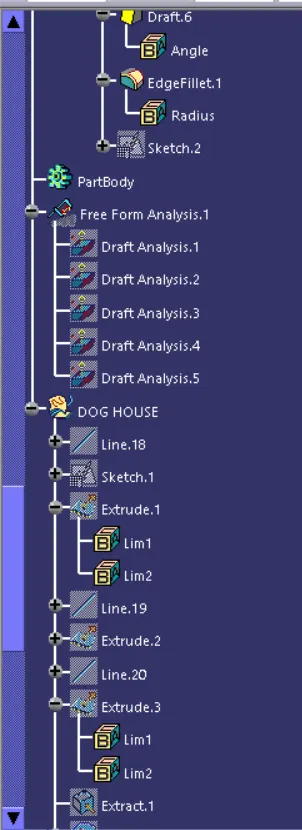
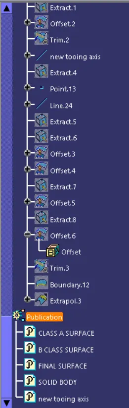
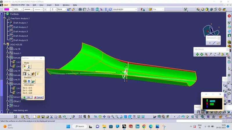
REPORT :- [THE CLASS A SURFSCE IS NOT PROPER ,THATS WHY CLASS B AND CLASS C SURFACE DRAFT ANALYSIS ARE NOT DRAFTED PROPERLY.]