Photo Realistic Rendering
Design Of American Chopper Bike
- OBJECTIVE :-
We study about the design of a bike aesthetics in solidworks. For reference i am taking an american chopper bike for desiging .American chopper bike is two wheeler.
Solidworks is 3-D softwer by dasault system solidworks is used to design new components, modify analysis , managing layout, drawing etc...
- INTRODUCTION :-
American chopper is an american based that is still on air on from 2003, prodused by pilgrim films and television.
This report contains a detailed explanation of design an american chopper bike using solidworks.In Solidworks, we use different module for different purpose. Here we use Sketch Module, Surface Module, Features Module, Evaluate Module, Render Module, Solidworks Visualize Module, etc. for designing American Chopper. In Sketch Module, we use Line Command, Rectangle Command, Circle Command, Arc Command, Spline Command, Fillet Command, Chamfer Command, Point Command, Trim Entities, Convert Entities, Offset Entities, Mirror Entities and Pattern Command. In Features Module, we use Extruded Command, Revolved Command, Swept Command, Lofted Command, Boundary Command, Extruded Cut Command, Revolved Cut Command, Swept Cut Command, Lofted Cut Command, Boundary Cut Command, Hole Command, Fillet Command, Chamfer Command, Pattern Command, Dome Command, Rib Command, Draft Command, Shell Command, Wrap Command, Intersect Command, Mirror Command, Move Command, Reference Geometry, Curves, Split Command and Combine Command.
- DESIGN METHODOLOGY :-
We have various components in chopper bike, First we need to design all the parts of chopper bike as required in the assembly.Assembling the parts using proper mates between them to fram the chopper bike. And apply proper redering and lighting to develop photoresalistic model images.
The steps followed in this process..
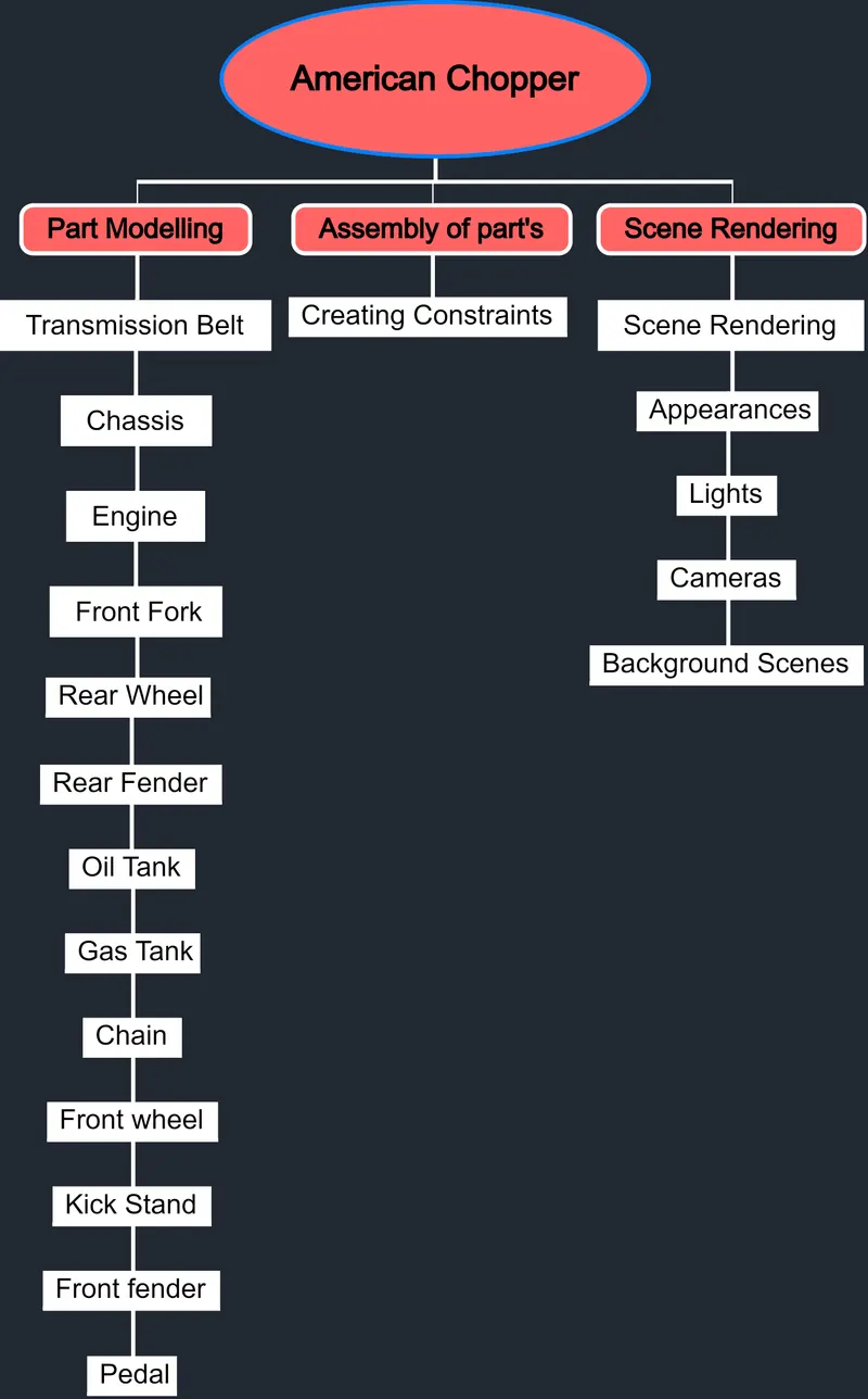
Fig.1 Design Methodology Flowchat
- Tools and feature :-
- Extrude: Extrude feature allows to from 3D solid body from surface or plane.
- Chamfer: Chamfer is used to give a sloped.
- Revolve: This feature allows you to revolve a closed sketch around a selected axis of rotation to from solid body.
- Fillet: Fillet is used to give rounded shapes to sharp edges.
- Shell: Shell tool hollows out a part and creater thin walled featuers on all sides, leaving the selected face open.
- Combine: Combine feature allows you to add two bodies to gether and keep the area that is common to both.
- Loft: To generate complex geomentry in single feature by specifying cross section made from faces and profiles of closed sketches.
- Dome: Domw feature is used to provied dome shaper to surface.
- Sweep: Sweep command is used to sweep a featuer along a provided curve to from a solid body.
- Mirror: Mirror featuer allow you to create an opposite hand vension of a part.
- Projected curve: This tool allows to create a projected curve, from two differnet curves the resultant curve is the intersection of surfaces formed by the two curves.
- Pattern: Pattern tool allows to create a patterns of desired parts / sketches along open or close curves,edges,surfaces etc.
- DESCRIPTION:-
- Parts of chopper bike;
Transmission Belt
Main function of transmission belt is to transmit power.
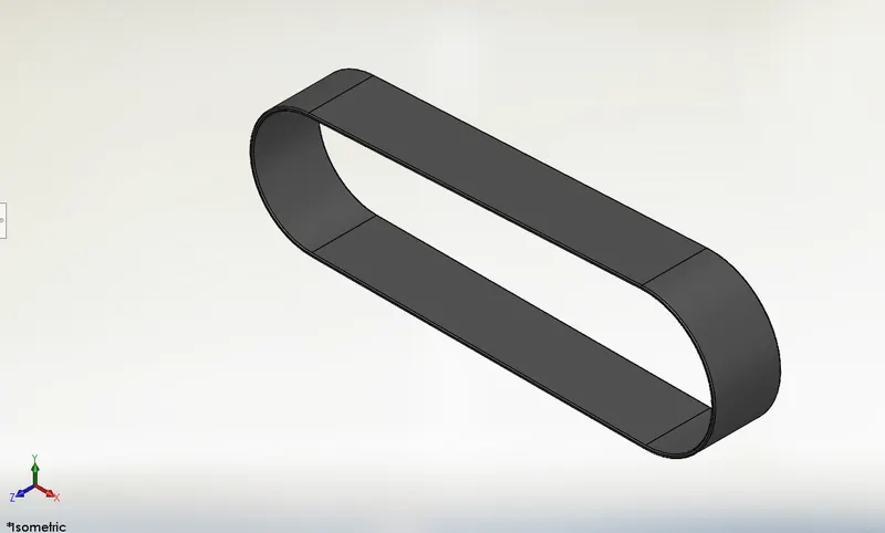
Fig.2 Transmission Belt
- Chassis
Chassis is the supporting frame of a vechicle on which various components of the vehicle are mounted.
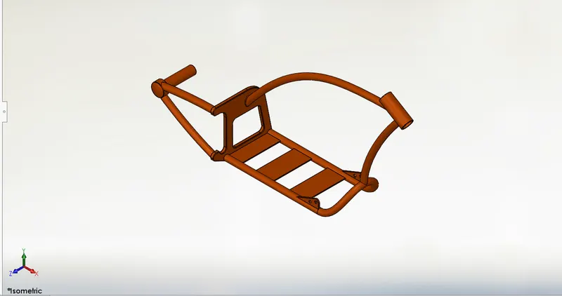
Fig.3 Chassis
- Engine
Engine is the power source of a vehicle.
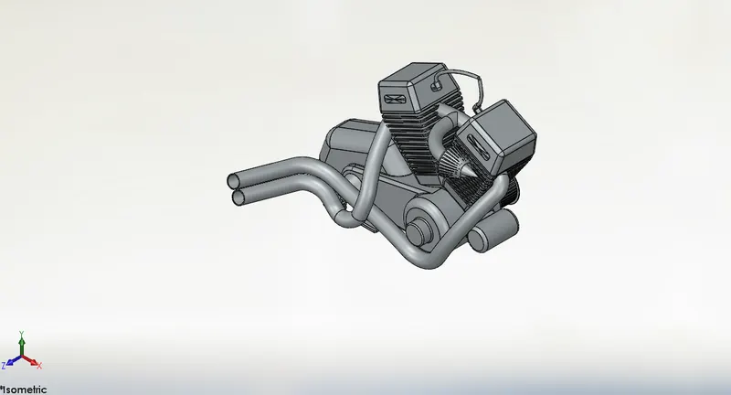
Fig.4 Engine
- Front fork
The fornt fork connects wheel and axle to the vehicle chassis.
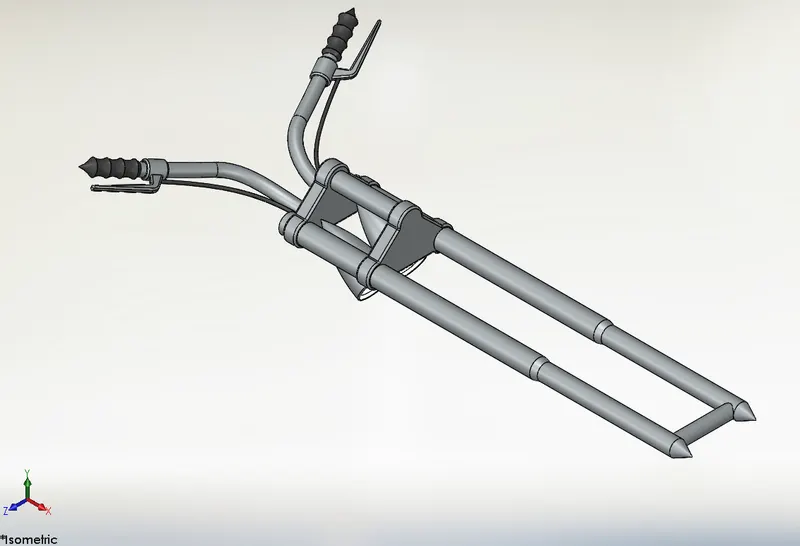
Fig.5 Front fork
- Rear wheel
A trassmission system that provides power to the rear wheels of a moter vehicle.
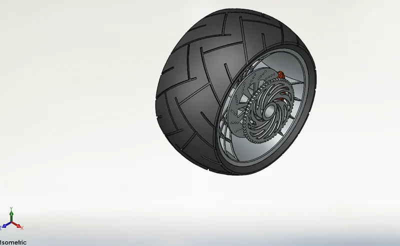
Fig.6 Rear Wheel
- Rear Fender
The primary purpose of the rear fender is to prevent mud,dust, and rocks from being thrown towards the rider or bike components.
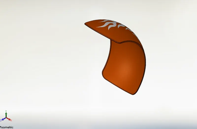
Fig.7 Rear fender
- Oil Tank
Its simply holds or store the oil.
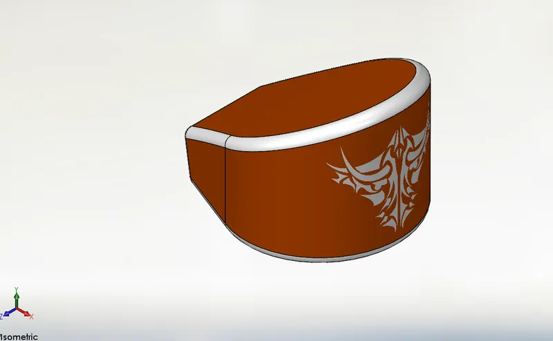
Fig.8 Oil Tank
- Gas Tank
Gas tank holds the fuel .and the fuel is stored and propelled or released (pressurized gas) into an engine.
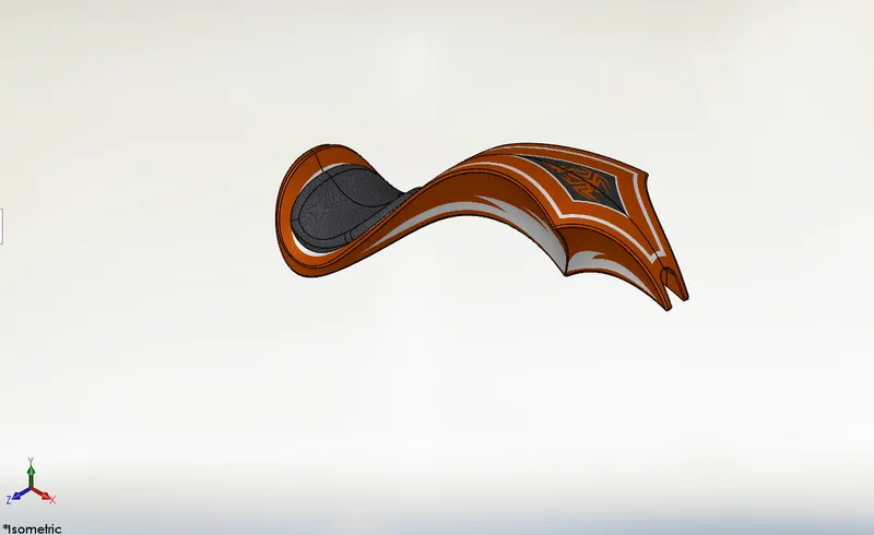
Fig.9 Gas Tank
- Chain
Chain is used to transmit power from the engine to rear wheel through sprockets.
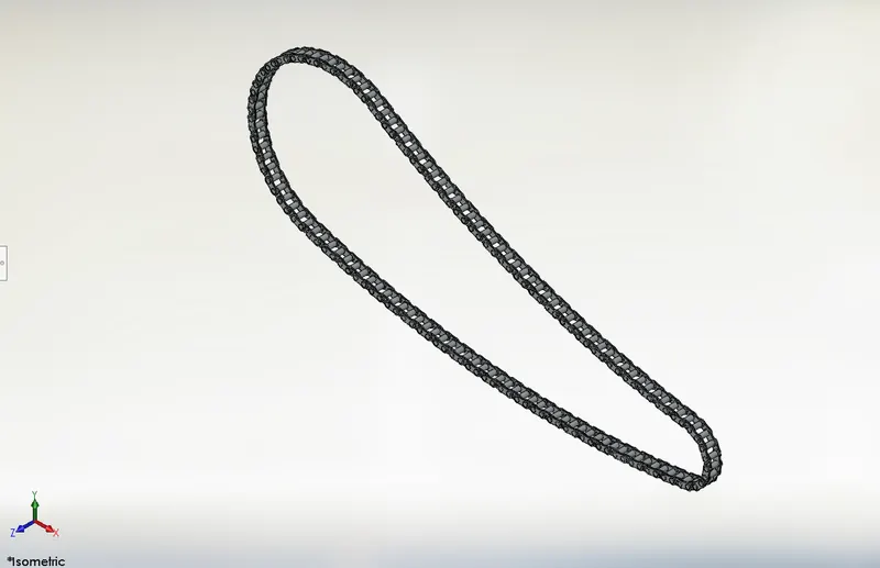
Fig.10 Chain
- Front Wheel
The front wheel is used to controlled by a lever near handgrip .And helps to turn the vehicle while moving.
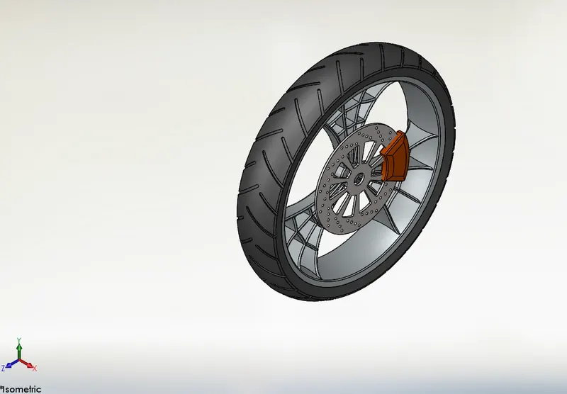
Fig.11 Front Wheel
- Kick Stand
Kick stand allows the bike to be kept upright without leaning against another object.
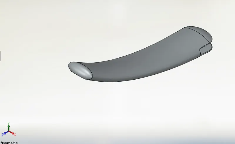
Fig.12 Kick Stand
- Pedal
pedals are used to operate brakes or switch gears in the vehicle.
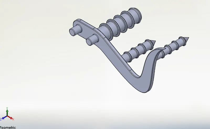
Fig.13 Pedal
- Front fender
The primary purpose of the fender is to prevent mud, dust, and rocks from being thrown the ride or bike components.
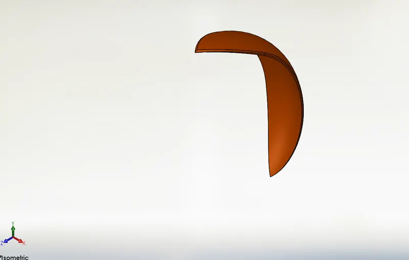
Fig.14 Front fender
- Assembly views:
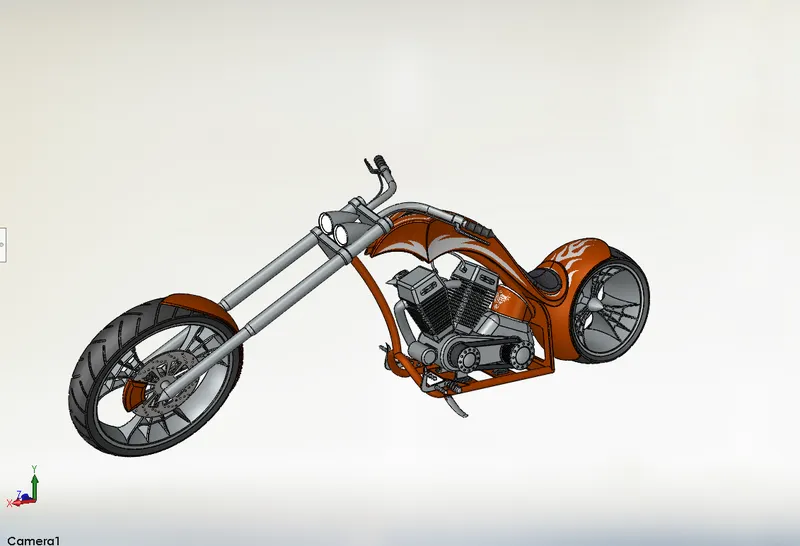
Fig.15 Camera view
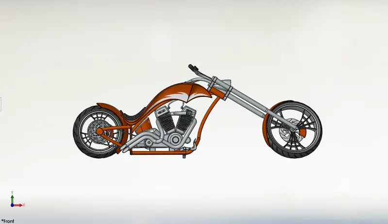
Fig .16 Front view
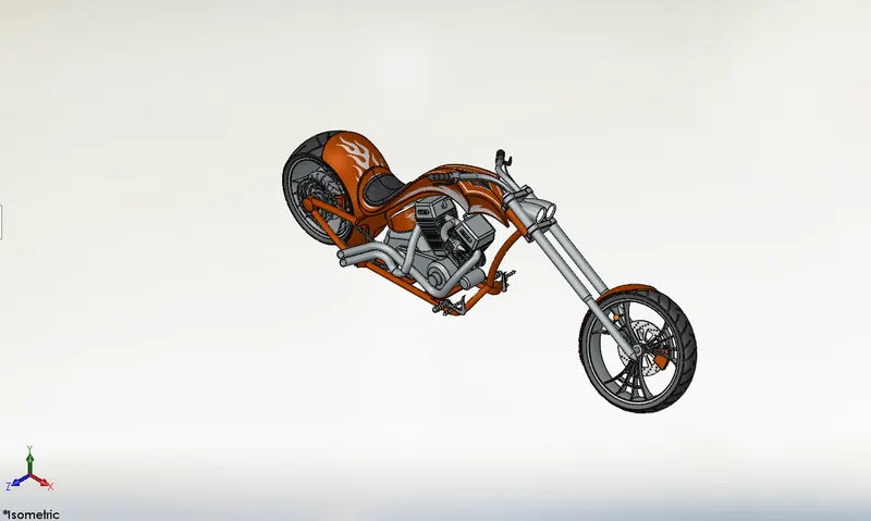
Fig.17 Isometric view
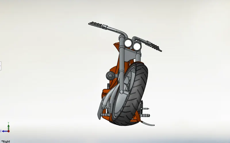
Fig.18 Right view
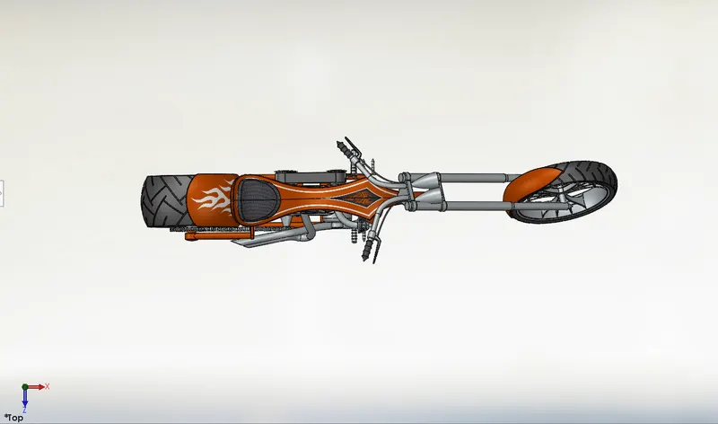
Fig.19 Top view
- Rendered images:
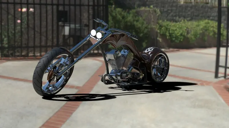
Fig.20 Render 1
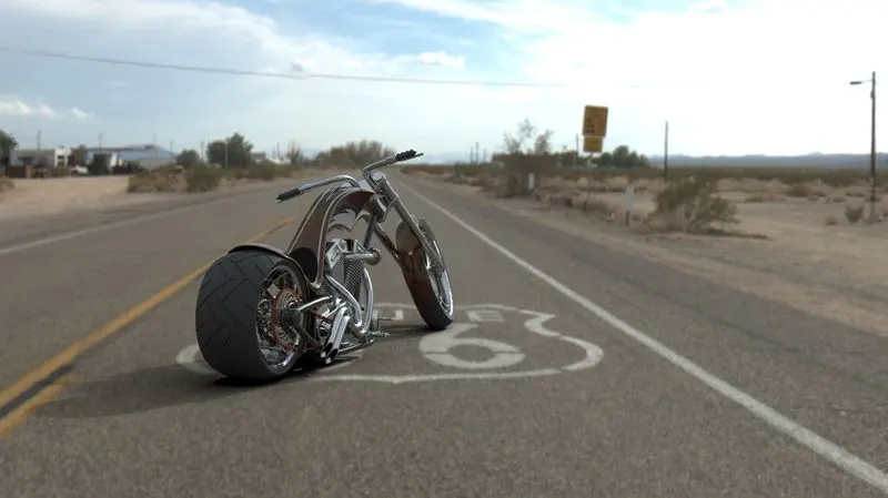
Fig.21 Render 2
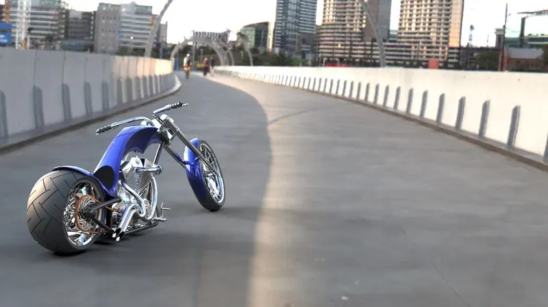
Fig.22 Render 3
- CONCLUSION :-
- A model has been developed with the help of Solidworks by using some global variables, dimension and equeation
- The users can update model just by changing ground clearance, Tire size, etc.
- In this way designer can perform tasks especially in the mechanical design.
- After this user are comfortable to design and modify different components.