Week 9 - Project - A pillar Design with Master Section
AIM:
To create a closed body using class A surface and master section to considering all design parameters then do the draft analysis using tooling axis.
Objective:
- Draft analysis the Class A surface
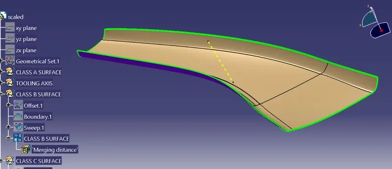
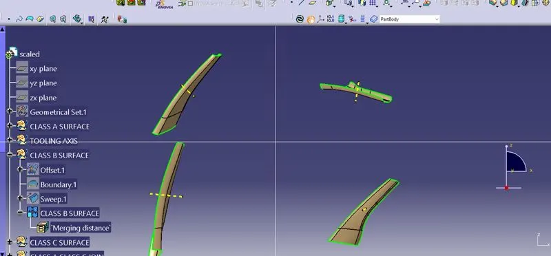
- Create Class B surface using Class A surface
- Create tooling axis using the master section
- Create closed body using surface
- Create DOG HOUSE using the master section given
- Do the draft analysis and ensure the part is manufacturable
MASTER SECTION:
Mster section are guides for design requirements which decides component package after the tecnical surface.
DRAFT ANALYSIS:
Draft analysis:
draft analysis is a techinque is used to analyze whether our part model created in catia V5 is manufacturable based on the draft condtion applied. Here the part should get easly removed from the mold.
No parts can be ejected from the tool if it is having straight 90 degrees profile from its base surface. Asmall draft angle provided to each an every area of the component inorder to get easly removal of component from the tool.
Here we are providing or assuming a direction in which component should eject in order to get easly removal of components
- Fisrt check the continuety of given Class A surface.
- Check three directions (X, Y & Z) and dicide which is the best possible dirction to produce a mold.
- At Z axis direction in the faces are either positive or negative so the Z axis we tacken as dummy tooling axis
Tooling axis creation:
Direction which mold opens or cavity opens.
create a point at center of base sutface and create axis sysytem on apoint create an intercection line along ZX plane on class A surface.
Then create a line along YZ plane which line is inclined to the intersection of class A surface
then use the bisection of both lines along with the center point
Extend the line that you want to create tooling axis for the model the do the draft analysis using the line axis.
Bisection Method commenly used in Master section given or created master section.
First we take an slightly 2 lines which is intersect on long distance disrection of tooling axis will be cavity open derection. then create a point on ZX plane and create a line using the intesection line. That is the tooling axis.
Draft analysing method:
insert-analysis -feature draft analysis. Select compass icon in draft analysis dialogue box and drag the compass and place it into the tooling axisselect to draft direction option switch to quick analysis mode see whether surface are passed draft angle or not.
class A suraface
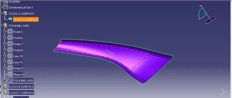
Draft Analysis of Class A:
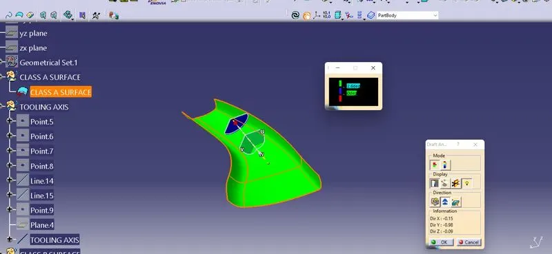
*From the draft analysis we cant get a proper Class A surface some portion have zero degree draft so we got class A surface is slightly improper.
When the draft analysis we used tooling axis created by using bisecting method as per given master section.
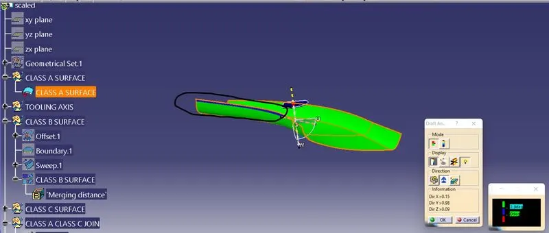
CLASS B SURFACE:
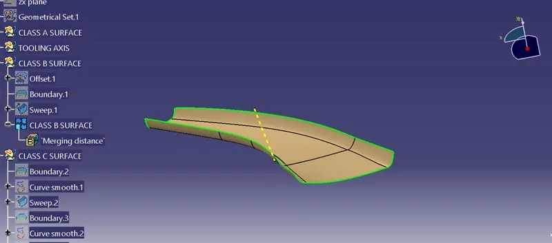
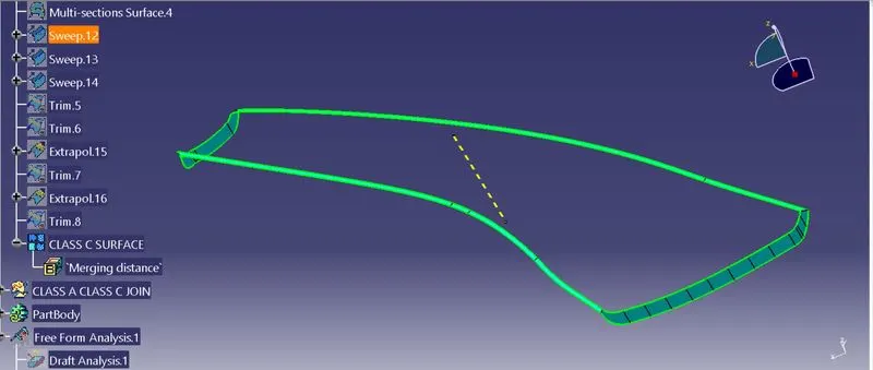
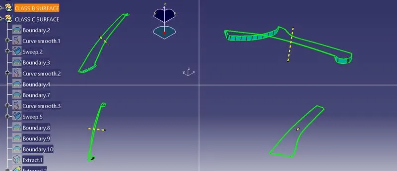
Class C surface
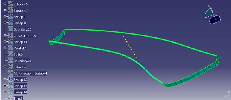
Closed surface:
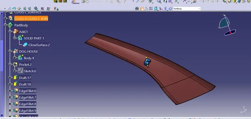
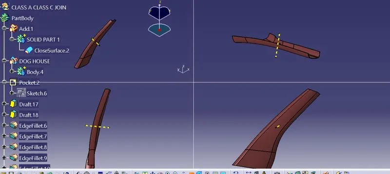
Draft Analysis of Closed body:
Draft analysis of Flange using 3 degree of draft angle
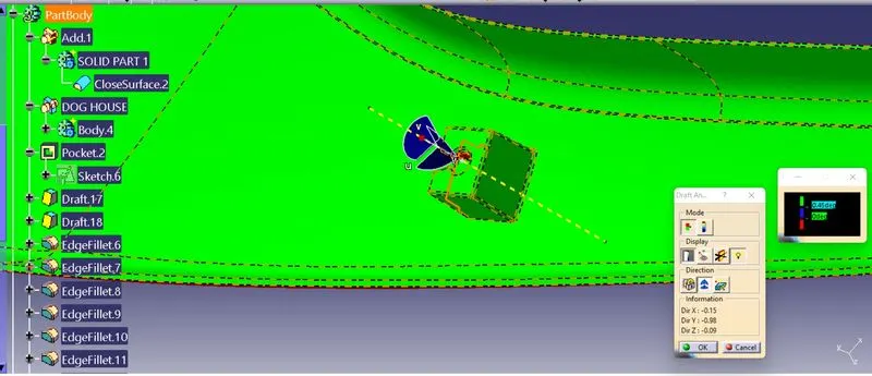
Draft analysis of Dog House outer surface using 1.5 degree draft angle
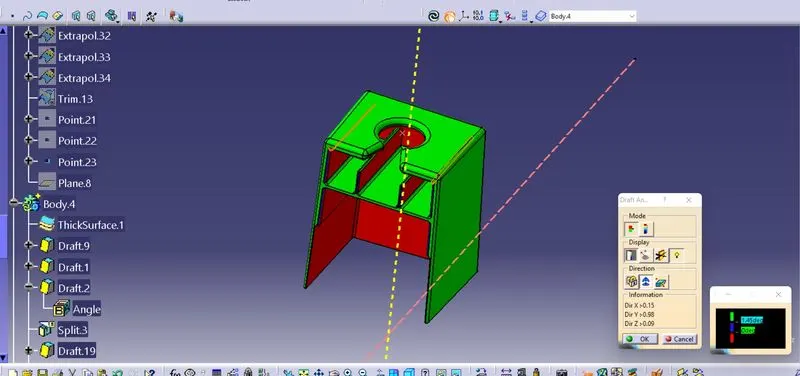
Draft analysis og Dog house inner surface of angle .5 degrees(using Side core axis)
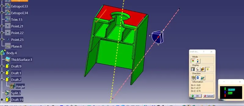
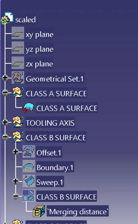
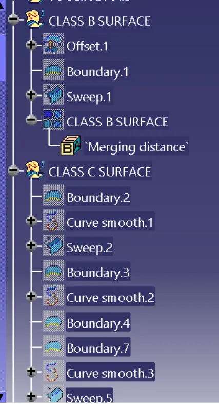
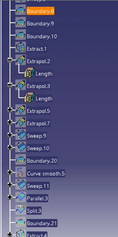
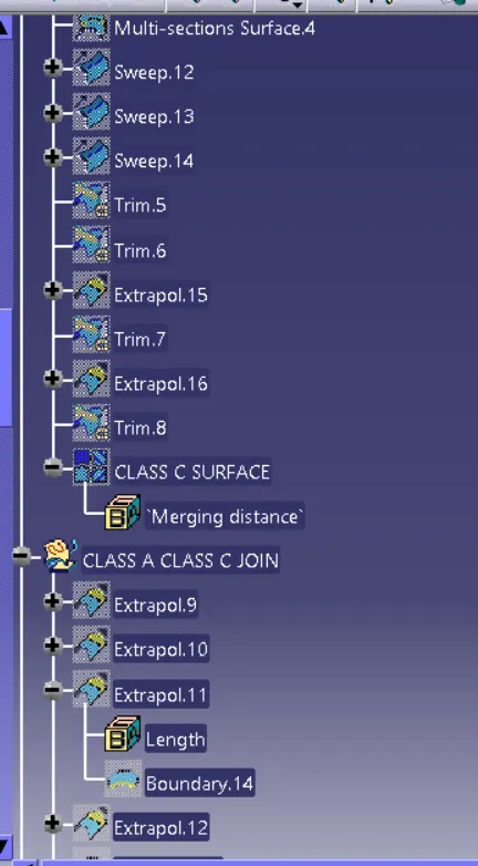
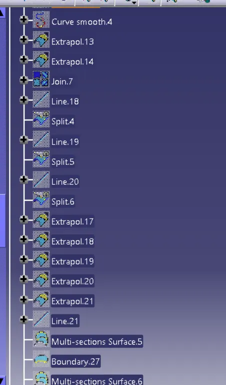
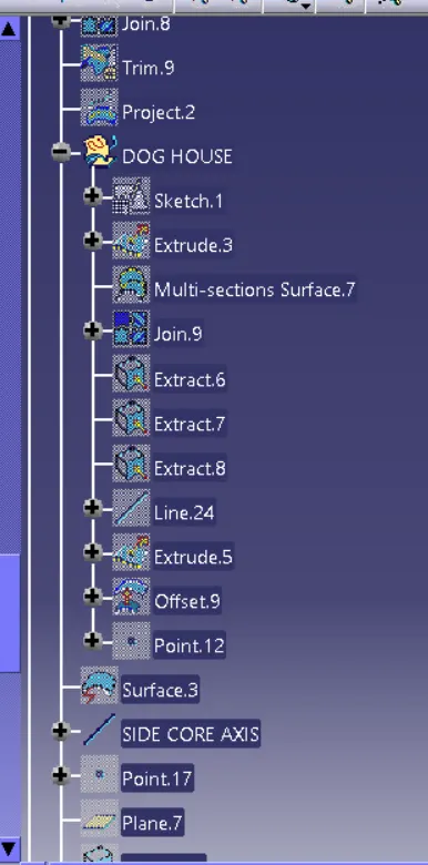
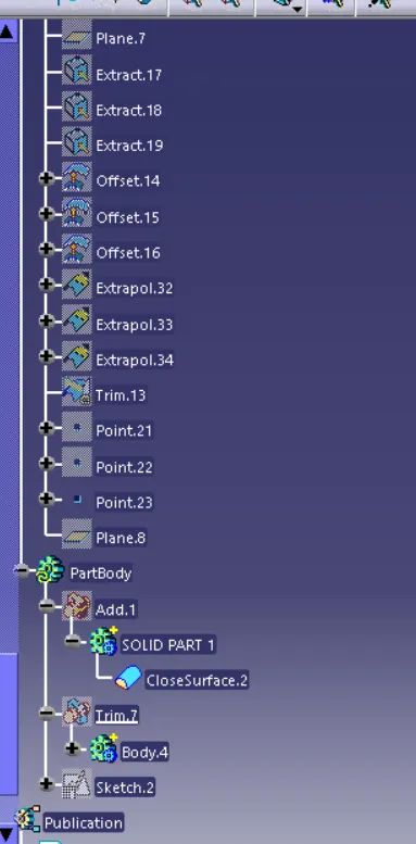
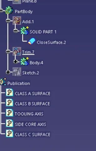
Tree stucture: