Week -2
https://drive.google.com/drive/folders/1YFeoQQ3TeDL0bpqV1osWXZitw41HdicS?usp=sharing
DOORBELL USING SOLINOID
AIM:
To create a Simulink model of doorbell using solenoid block
BASIC COMPONENTS USED TO MAKE DOORBELL CIRCUIT
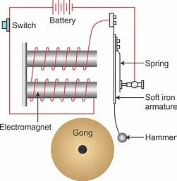
SOLINOID:
Solenoids are basically coils of wire. These generate magnetic field which strives a force over a metallic element. This happens when we apply electric current to the solenoids. Solenoid helps the Energy to convert into action instantly. Therefor, these work decently for those application which requires immediate action.
Actually it generates a magnetic field for creating linear motion from the electric current With the use of magnetic field
THE GIVEN CONDITION
In the arrangement when the switch is in on condition the electromagnet receives magnetic power and form the battery and produce magnetic field that effect pulls the metal arm to hit bell producing sound.
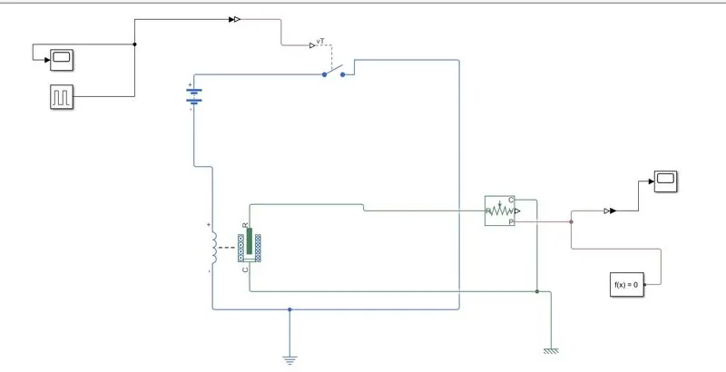
BLOCK DIAGRAM :
PULSE GENERATOR:
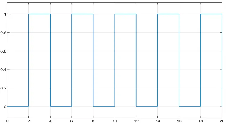
The pulse generator block generates square wave pulse at regular intervals. The block waveform parameters, Amplitude, pulse width, period and phase delay, determine the shape of the output waveform. The following diagram shows how each parameters effects the waveform
BATTERY:
In Battery have a positive and a negative terminals and it is an electrical energy source
SWITCH:
In the switch block which controlled external physical signal
SOLINOID BLOCK:
Solenoid block connected with switch and battery and electrical circuit will be formed.
The solenoid Block represents the electrical characteristics and generated force for the solenoid
IDEAL TRANSLATIONAL MOTION SENSOR BLOCK:
Ideal translation motion sensor connected with solenoid block ‘R’ to oserve the physical movement of plunger
Connection R an C are mechanical conserving ports that connect the block to the nodes whose mention id being monitored. Connection V and P are physical signal output ports for velocity and position, respectively.
The block positive direction is from port R to port C .This means that the velocity is measured as v = vR-vC, where vR and vC are the absolute velocities at ports R and C respectively.
Port C is connected with mechanical translational reference.
SCOPE:
Scope is connected with ideal translational motion sensor to get the output plot
PS-Simulink converter:
The PS-Simulink converter block converts physical signal to a Simulink output signal. Use this block to connect outputs of a physical network diagram to Simulink scopes or other Simulink block.
Simulink-PS converter:
This block converts Simulink signals for operational use in model.
ELECTRIC REFERENCE BLOCK:
The Electric Reference block represents an electrical ground. Electrical conserving ports of all the blocks tat are directly connected to the ground must be connected to an electrical reference block. A model with electrical element must contain at least on electrical reference block.
MECHANICAL TRANSLATION REFERENCE BLOCK:
Mechanical rotational reference block represents a reference point or frame, for all mechanical rotation ports. All rotational ports that are rigidly clamped to frame must be connected to a mechanical rotational reference block.
SOLVER CONFIGURATION:
Each physical network represented by a connected Simscape block diagram requires solver settings information for simulation. The solver configuration blocks specifies the solver parameters that your model needs before you can begin simulation.
EXPLANATION
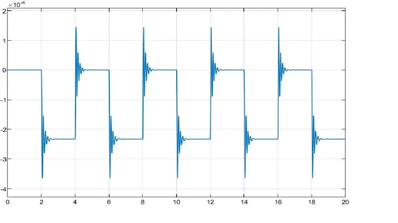
First we giving inputs to the pulse generator setting up the amplitude and time period 4 sec and phase width 50% and phase delay 2 sec the simulation start from the unengaged condition of switch. The signal from pulse generator was converted from the Simulink PS converter and is given as input to the switch. A solenoid is introduced and battery is connected to it . The voltage battery connected was made as the same as that of the rated voltage of the solenoid . The switch also connected to the same circuit. The position of solenoid plunger is measured using an ideal translational motion sensor connected to the circuit. Initial position was set to 5mm in translational motion sensor. Both mechanical and electrical reference were connected to the respective circuit. The output from ideal translational motion sensor is converted using a PS-Simulink converter and given to the scope to display the results. Th scope was also connected to input device to display the input signal. The spring constant and damping parameters of the solenoid block was altered to obtain desired graph.
CONCLUSION:
The conclusion is the above result that we have successfully simulated doorbell mechanism operated by solenoid with given condition as we can saw in above graph
INPUT GRAPH
OUTPUT GRAPH
THERMISTOR
AIM:
Create a Simulink model of thermistor to sense the temperature of a heater & turn off the fan.
Blocks Used in models:
- Signal builder
- Controlled temperature source
- Thermistor
- Solver configuration
- Resistor
- Voltage Sensor
- Constant
- PS-Simulink converter
- Simulink-PS converter
- Switch
- Controlled voltage source
- DC Motor
- Ideal Rotational Motion sensor
- Display
- Scope
Signal Builder:
It used to create interchangeable signals group of linear signal source. We can change the signal amplitude and frequency manually. We can change the waveform in different condition
Controlled temperature source:
This block represents an ideal source of thermal energy that is powerful enough to maintain specified temperature different across source regardless of heat flow consumed by the system. Connection at point A & B are the inlet and outlet ports respectively S is the physical signal port through which controlled signals that drive the source applied.
Thermistor:
This is a thermal resistor, and combination of thermal and resistor. It s a type of resistor which depends upon temperature
Resistor:
This is the linear resistor
Voltage sensor:
This device converts the voltage measured between two points of an electrical circuit into physical signal proportional to the voltage
Voltage Source:
It voltage source with DC current.
Electrical Reference
The Electric Reference block represents an electrical ground. Electrical conserving ports of all the blocks tat are directly connected to the ground must be connected to an electrical reference block. A model with electrical element must contain at least on electrical reference block.
DC MOTOR
It is a model which having torque and speed and load these are working under spesified condition we applied
IDEAL ROTATIONAL MOTION SENSOR
It is a model block which used for mechanical rotational motion sensing
Display
It is display which used to saw the result
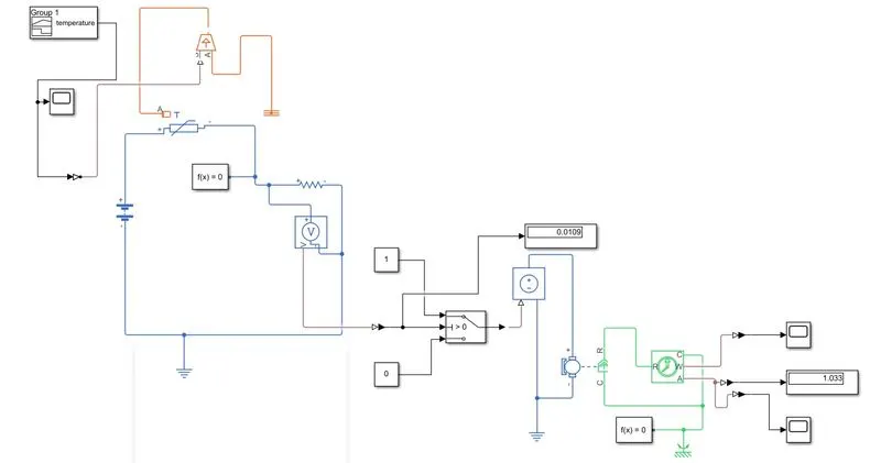
BLOCK DIAGRAM
EXPLANATION
A thermistor used along with a resistor and a battery to create a circuit. The thermistor connected to an ideal temperature source and a voltage sensor is provided across the resistor to measure the voltage difference and the temperature source is provide with the input signals as per the given conditions in the question.
Condition:
0-10 sec-temperature is 293.15(20°C)
10-30 sec – temperature 300.15k(27°C)
30-50sec -temperature 296.15k(23°C)
INPUT GRAPH
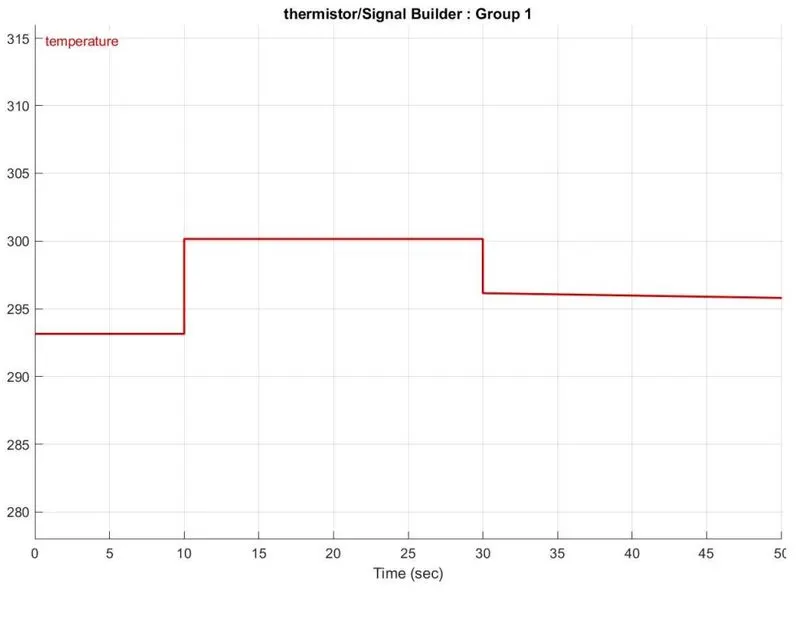
Here the temperature is converted to Kelvin because the signal converter didn’t have the option of degree Celsius. The battery and voltage sensor are connected in series and resistor is connected in parallel to voltage sensor. The solver configuration is also used to specify the solver parameter. The electric reference is also used to ground the electric system.
The voltage sensor is connected to switch to control the fan with the help of PS-Simulink converter to convert signal in Simulink input and we connected to display to show the simulation value. In the switch decide threshold value if the temperature is above the limit , it gave 1 as output which means witch on and the temperature below the limit the I gave 0 as output means switch off.
CONCLUSION:
We can conclude that from the above output results of our Simulink model of thermistor and we were able to switch on the fan at a particular temperature as per given condition.