Week 9 - Project - A pillar Design with Master Section
A PILLAR DESIGN WITH MASTER SECTION
AIM:
The main objective of this challenge is to understand the given master section to create a solid body and B-side features for a given class A surface, by considering all the design parameters.
MASTER SECTION:
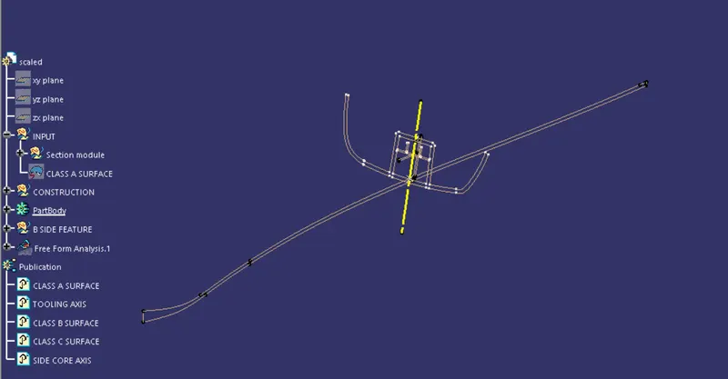
Master sections are the guides for design requirements which decide the component packaging after technical (Styling, Concept or Class-A) surfaces. It helps easy to design a component without complete 3D. The given master section as shown in below.
TOOLING AXIS CREATION:
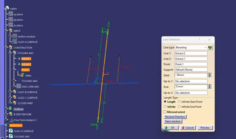
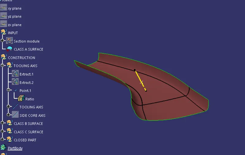
To create the tooling axis, I used the 'bisecting' line method. Initially, I created two lines on the master section by using 'point to point line' and then I created a bisecting line at the centre of those two lines by using bisecting line option in the line command.
DRAFT ANALYSIS FOR CLASS A SURFACE:
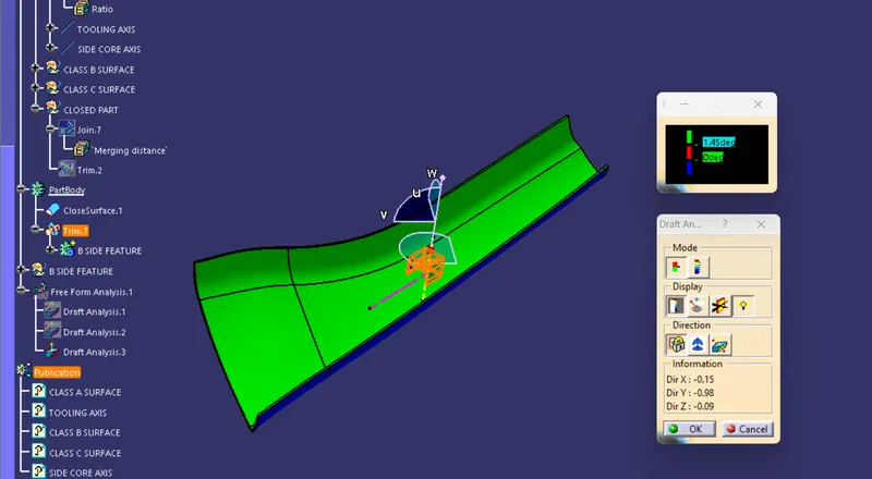
The craft analysis check is performed on the class A surface before we create the solid part from that class A surface, to check whether the given class A surface is drafted properly or not. The draft angle for a plastic component is 0.5deg to 3deg).
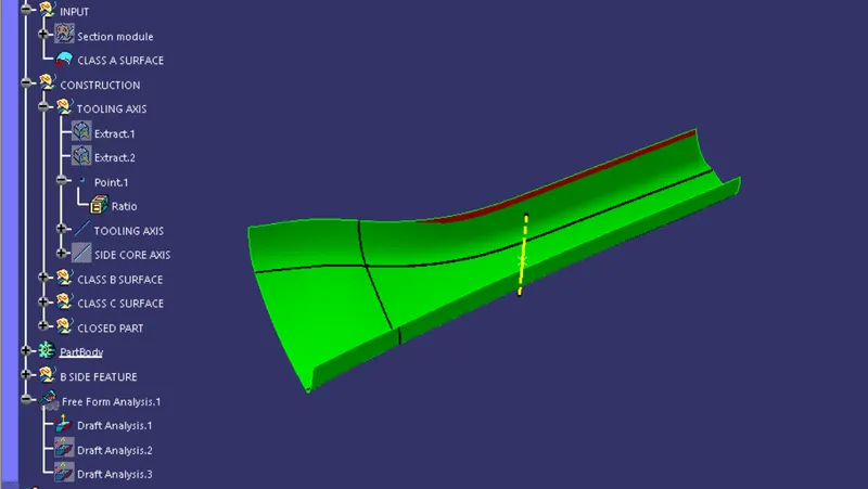
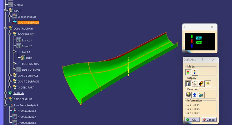
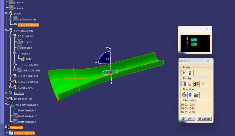
In the below image to as shows for ensure the how much of draft angle is to be in class a surface for manufaturing consideration. Initially, I gave a draft angle of 2.5deg and still some faces are not cleared later I gave a 2deg draft angle to check if all the faces are cleared or not. Still some faces are not cleared with 2deg also, so I reduced the draft angle to 1.9deg, with a 1.9deg draft angle all the faces in class A are cleared properly.
CLASS B SURFACE:
To create the class B surface initially, I measured the thickness of the master section (2.5mm). I offset the class A surface 2.5mm to the inside direction. The styling fillets on the class A surface are not offset properly, it created the patch on the offset surface. I used the sweep command to close the patch on the offset surface
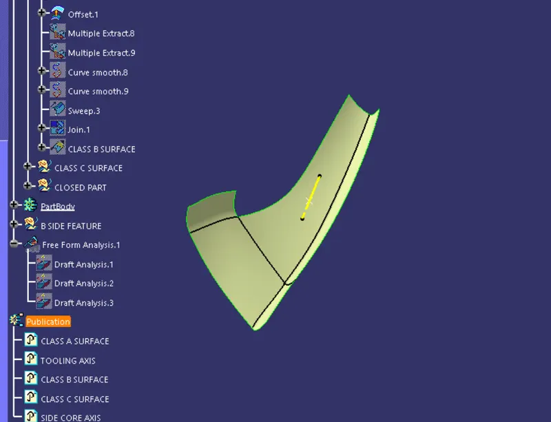
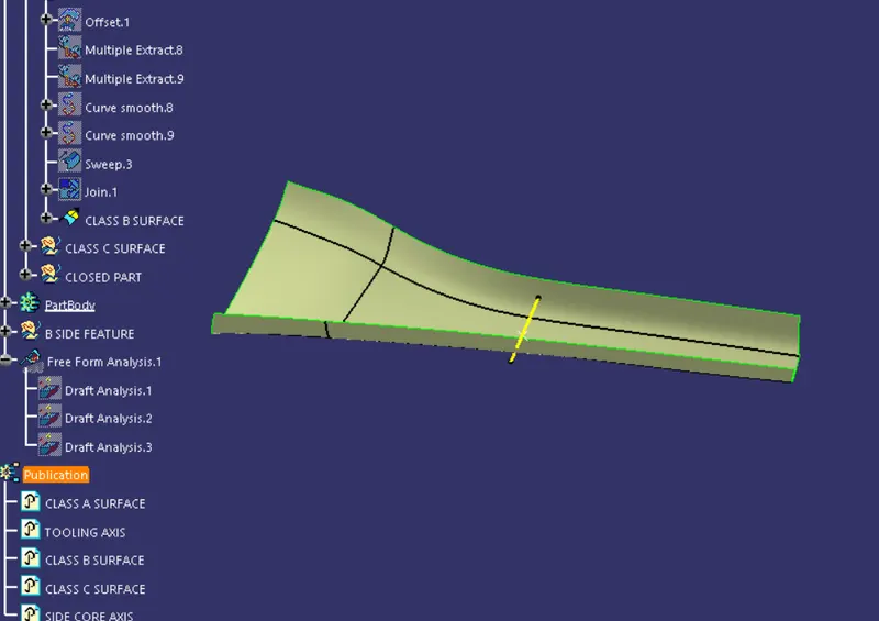
CLASS C SURFACE:
To order to create the class C surface, I used the sweep command. I sweep the class A surface edges along with referencing the surface for 4mm inside with 90deg. After the creation of the class C surface, the surface edges are needed to be extrapolated to intersect properly from all 4 sides. I trim the surfaces which extrapolated, to get the closed class C surface.
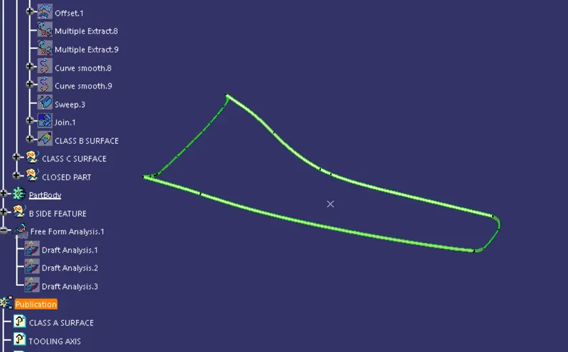
CLOSED PART:
I joined the class A surface and Class C surface to get a single surface of class A+C surfaces. I trim the Class B surface with class A+C surface join, to get the closed surface to create the solid body.
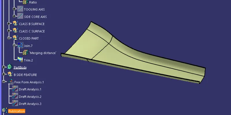
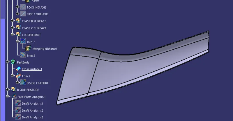
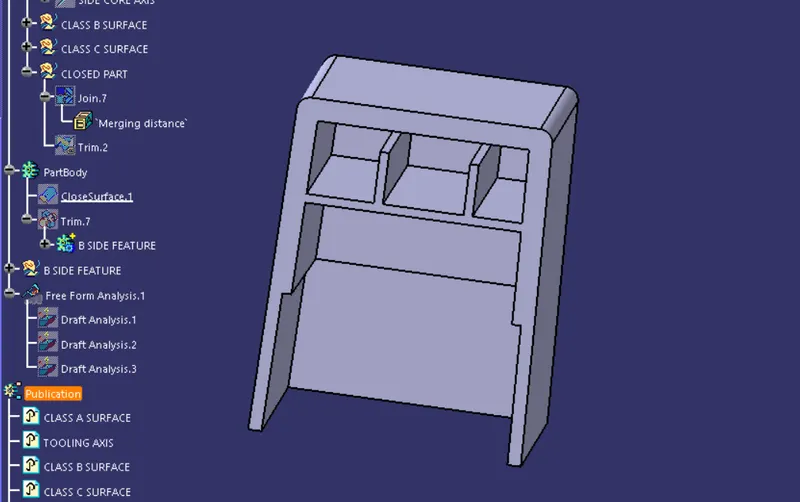
DOG HOUSE CREATION:
To create the dog house on the B-side, I extracted the lines on the master section and I create a plane to extract the lines concerning the master section.
DOG HOUSE:
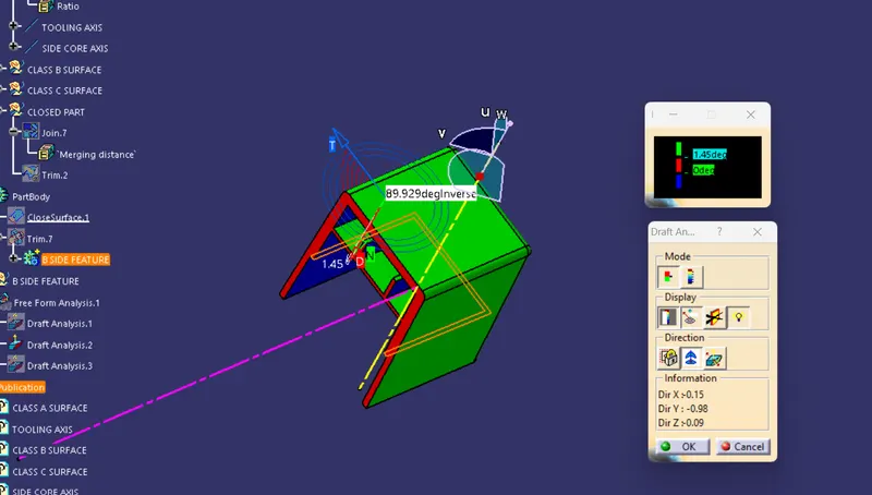
DRAFT ANALYSIS OF DOG HOUSE:
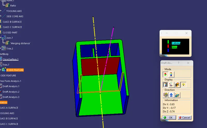
Draft analysis towards the side core axis:
I added the dog house to the main part body of A pillar solid.
SOLID BODY OF A PILLAR WITH DOG HOUSE:
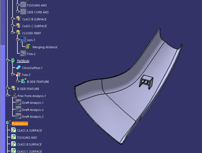
DRAFT ANALYSIS OF SOLID PART:
The draft analysis is used to check the surface draft angel and to know whether all the surfaces are drafted properly or not.
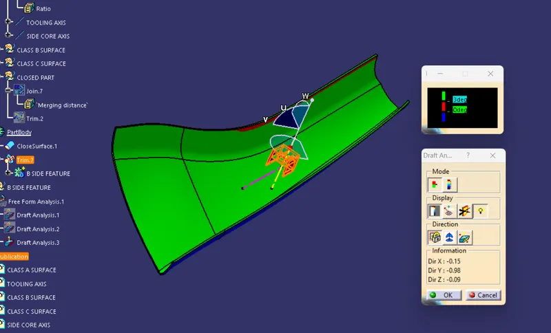
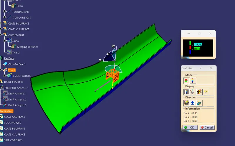
Draft analysis with the dog house,