Week 9 - Project - A pillar Design with Master Section
A pillar Design with Master Section
Aim:
Follow the master section for thickness and to create the Closed volume
Condition:
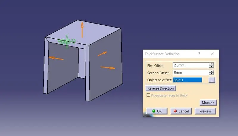
Thickness of the component = 2.5 mm
Draft angle = 3°
Input:
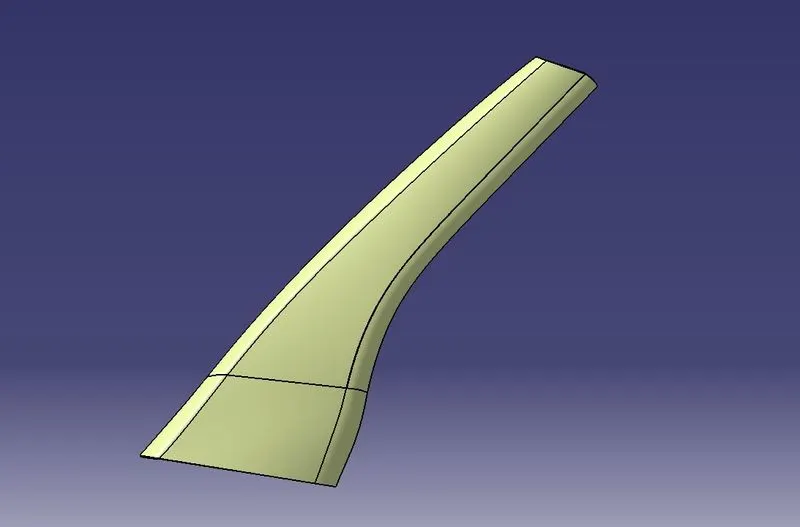
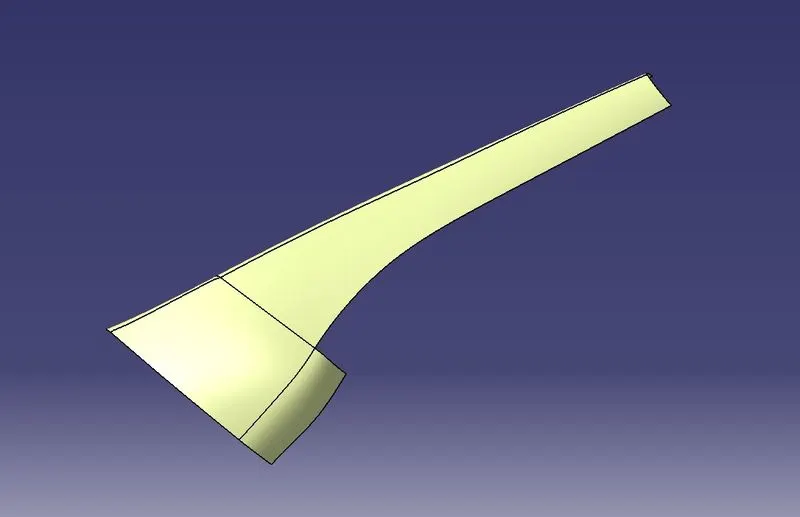
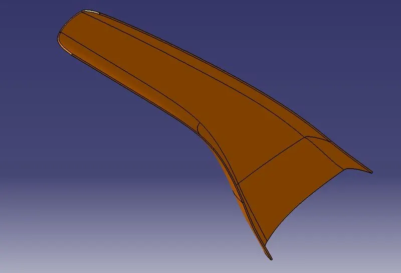
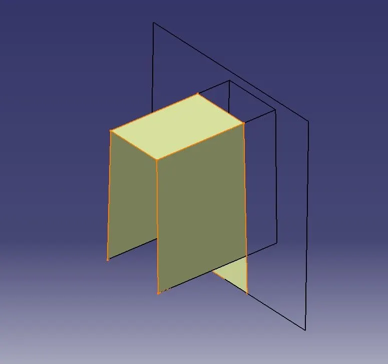
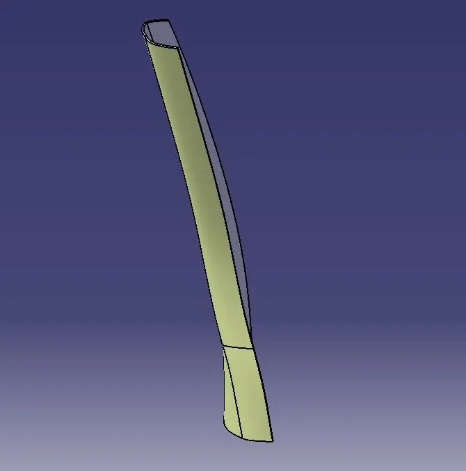
The following surface is given as the input for the component creation.
Input checking:
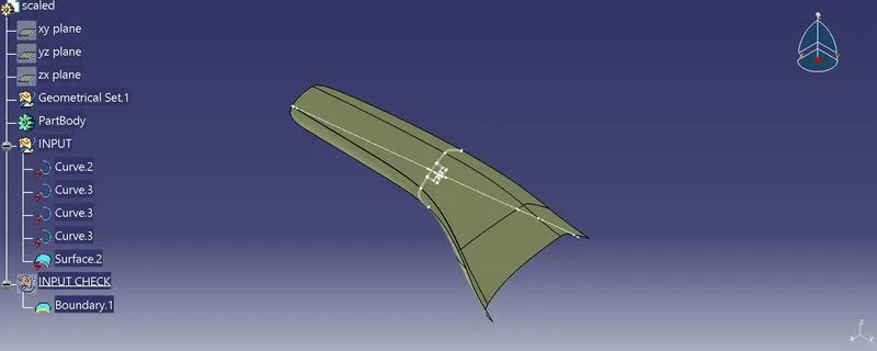
The given input surface is checked using boundary comment the boundary of the surface is are fully closed or not. If there is any open boundary make sure close it properly.
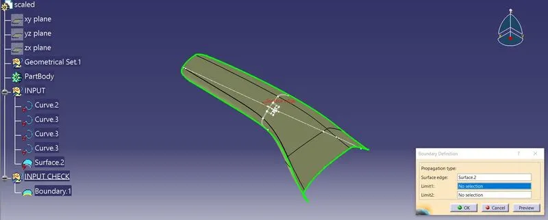
The given input is fully closed condition. So there no problem in creating class B surface.
Creation of Tooling Axis:
Tooling axis is the line represents the mold open and close direction at the time of component manufacturing.
If a component has flat surfaces, then the tooling axis identified by visually, otherwise intersection method is used to find the tooling axis of component.
Here, given surface has inclined walls so intersection method is used to create tooling axis.
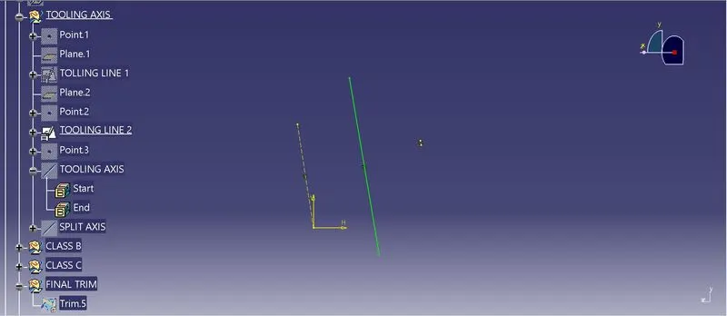
In here the master section is given so it is representing the both class A and B surface of he body. From the given master section, the dog house lines are extracted and using Bi-sect method tooling axis created shown like below
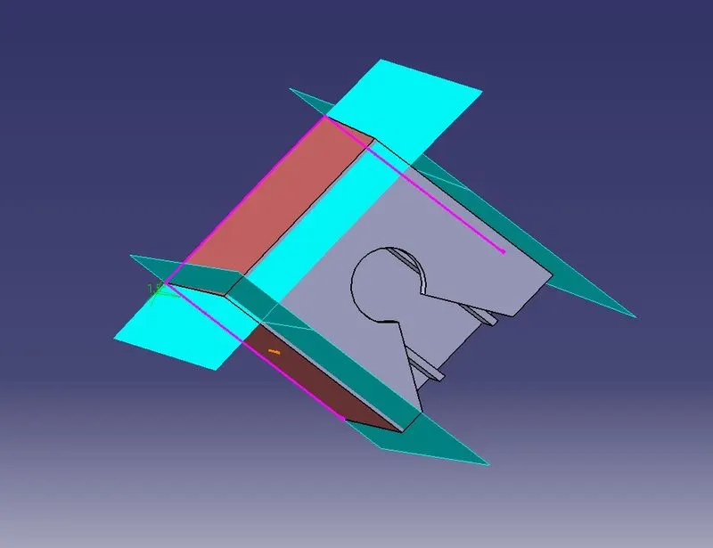
Thru point plane created from dog house. In that plane dog house section line projected and by intersection method Tooling line 1 created.
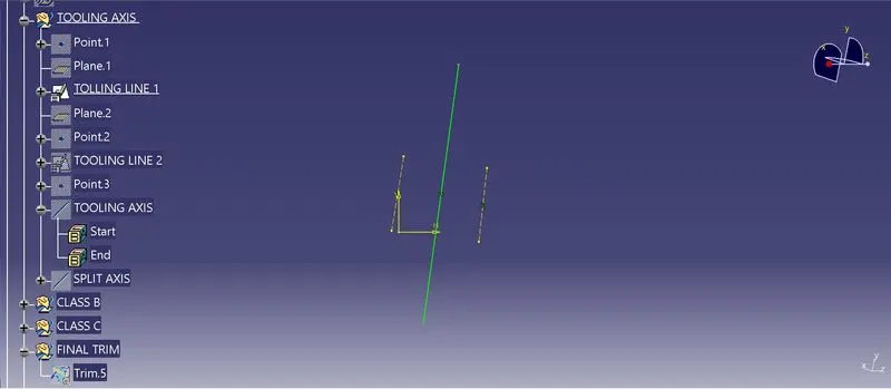
Tooling axis line 2 is also created by same method.
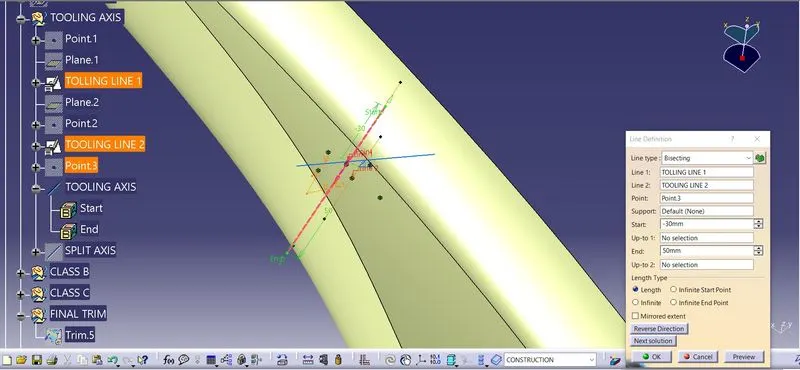
Main Tooling axis for mold open and close is created by Bisecting Tooling line 1 and 2 shown as per below image.
Draft Analysis of Class A surface:
Drafting analysis shows that when component ejected from the mold die whether the component removed smoothly without creating any damage or scratch on the surface of the component.
The minimum draft angle applied on the component is 0.5°. But it need high precision and it increases cost of the mold.
In industry 3° draft angle is used for optimal solution for component ejection.
Here, draft analysis is done with respect to 3° angle.
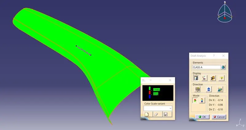
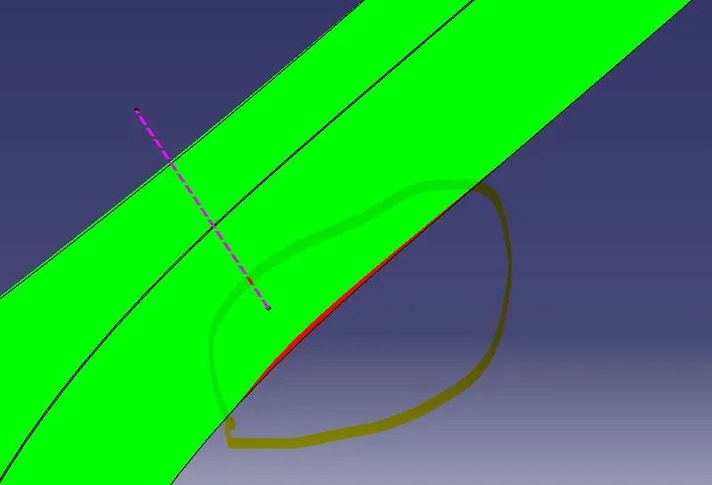
The draft analysis of class A surface shows that a small portion of class A is not clearing the condition for creating component. Which is shown above
The green color shows the given input class A surface has good positive draft effect. The red color shows surfaces are not clearing mold ejection condition that means the given class A need modification for mold ejection.
Where modification of class A surface need to consider with customers.
In this challenge after considering faculty further process done.
Creation of Class B:
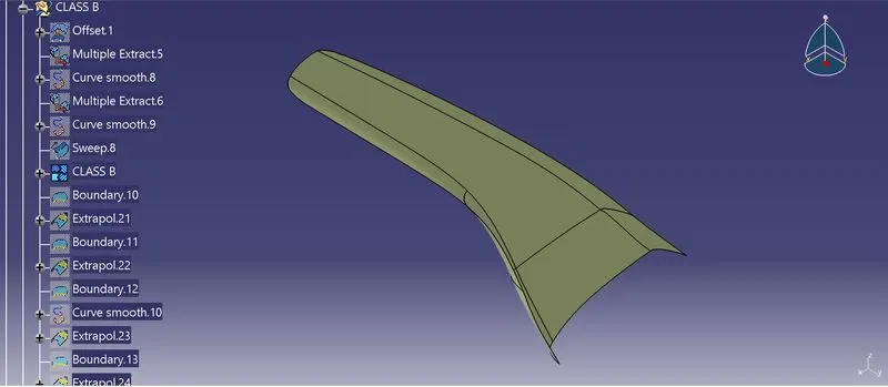
In here direct offset used to create the class B surface and done some patching work to complete the class B surface.
After offsetting the class A surface 2.5mm, the patching work is done by using the sweep command.
Patching needed area
After patching work done all the surfaces are joined together an created into single surface shown like below.
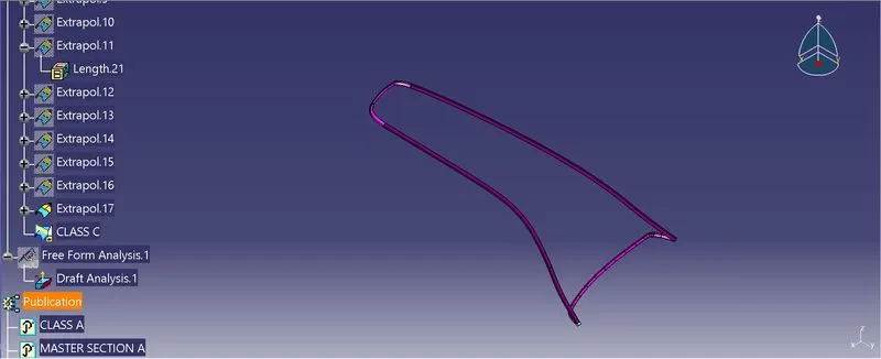
Class C surface:
- For creating class C surface, we have extracted the boundary of Class A using multi-extract and then converted to smooth curve.
- Now this smooth curve is swept along the draft direction with a 93deg perpendicular to CLASS A surface.
- In some places not smooth class C surfaces not formed, In those places multisection command used create the surface.
- Finally, the sweep surface and multisection surfaces are joined into single surface by join command.
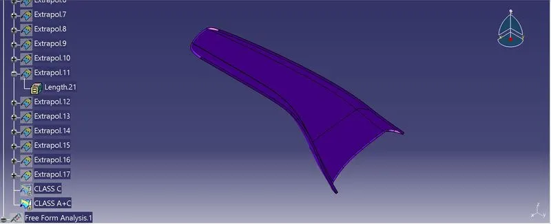
Class A + Class C
By, joining the class A and class C this surface formed for the final trim operation.
Class A + Class B + Class C
For this we have trimmed the Class B surface with Class A+C surface using trim feature. Then the fully closed surface is formed.
Dog House creation:
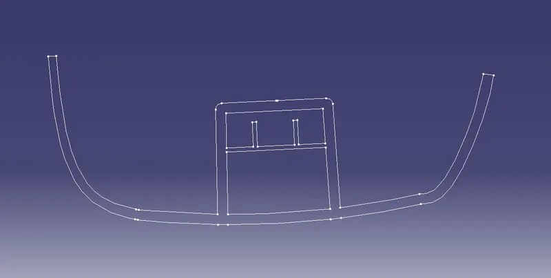
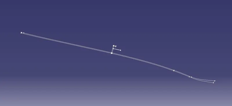
The given master section is assumed as A and B.
Master Section A
Master Section B
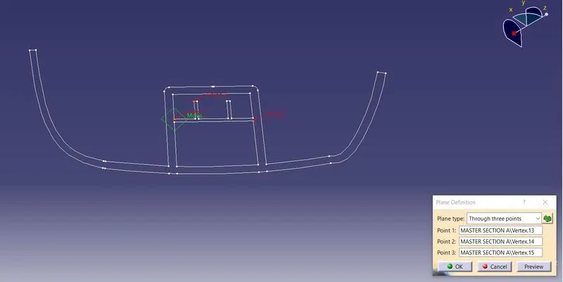
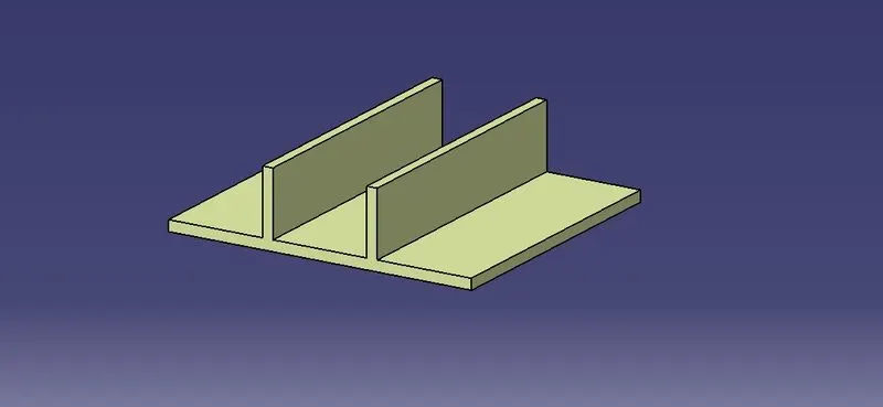
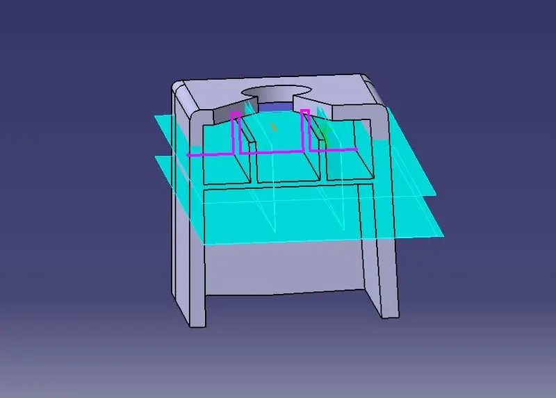
A plane is created by three-point method. The points are selected from master section A. In that plane dog house inner side sketch in drawn. This is sketch is extruded required length.
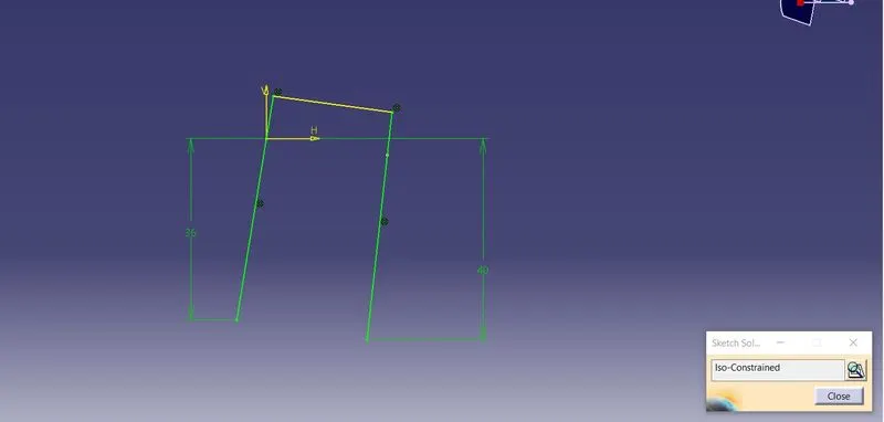
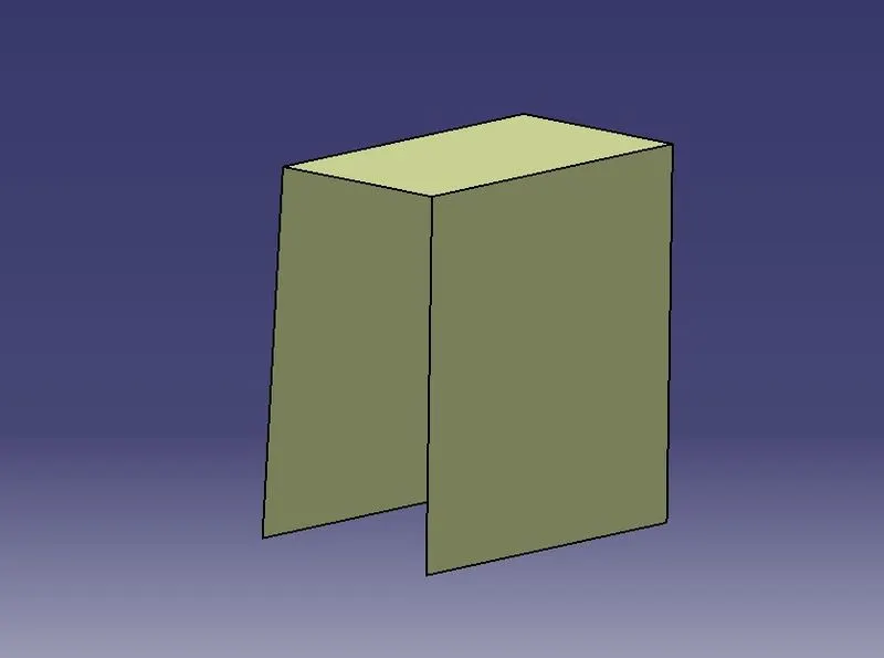
Another plane created in master section B. In that plane dog hose length is sketch. This sketch extruded and extrapolated.
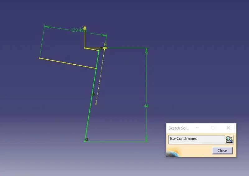
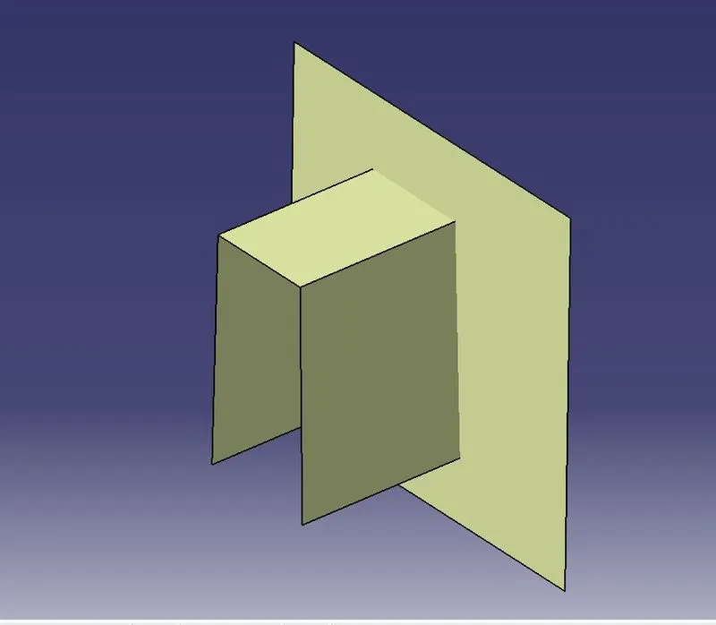
These two surface surfaces are trimmed and formed inside of dog house. Then this surface is thickened 2.5mm of master section thickness.
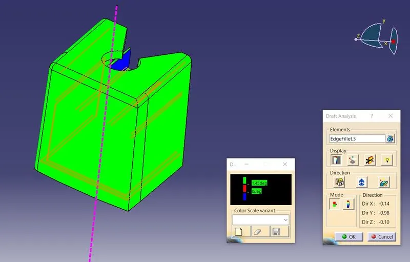
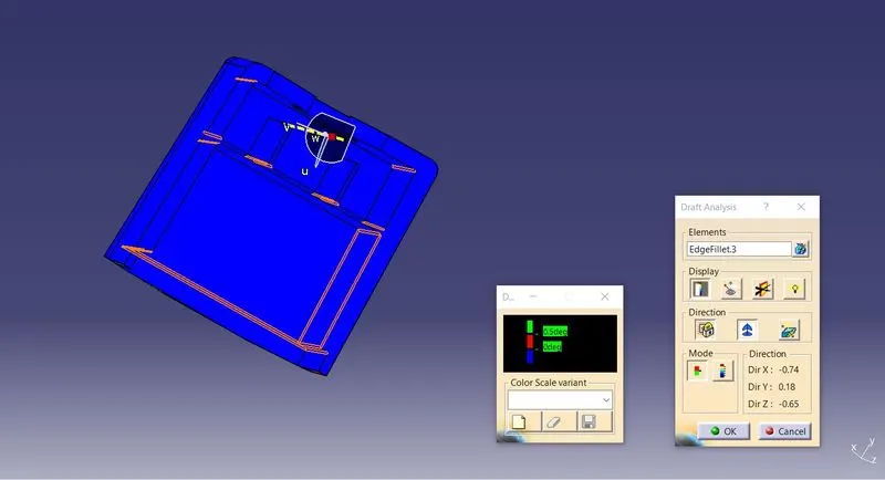
After that 1.5 Deg draft applied to side walls of dog house outside. Inner profile is created as per the given input drawing. Inside of dog house 0.5 Deg draft applied. Required places fillets are applied as per design requirement.
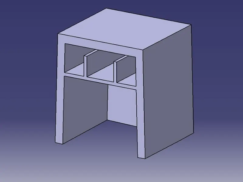
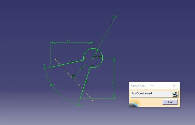
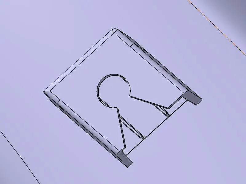
Outside Draft
Inside Draft
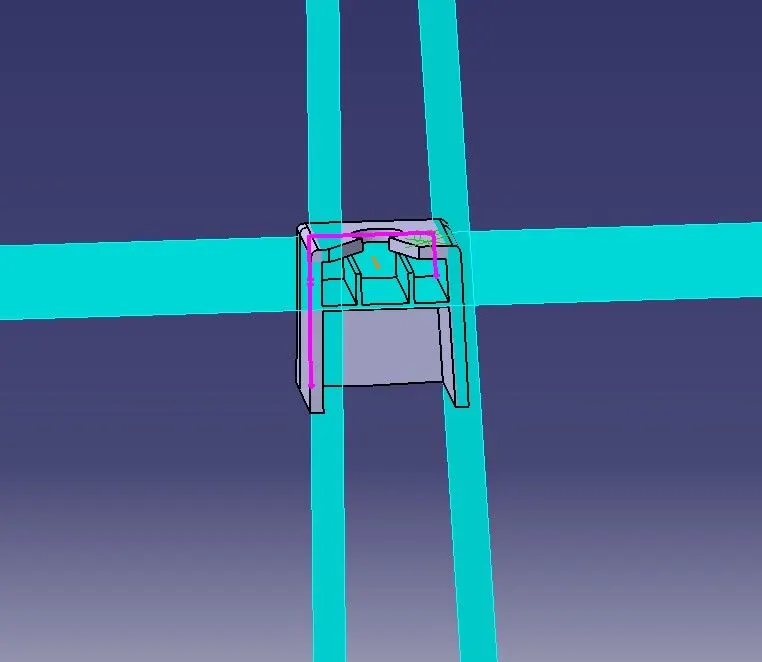
Side core axis:
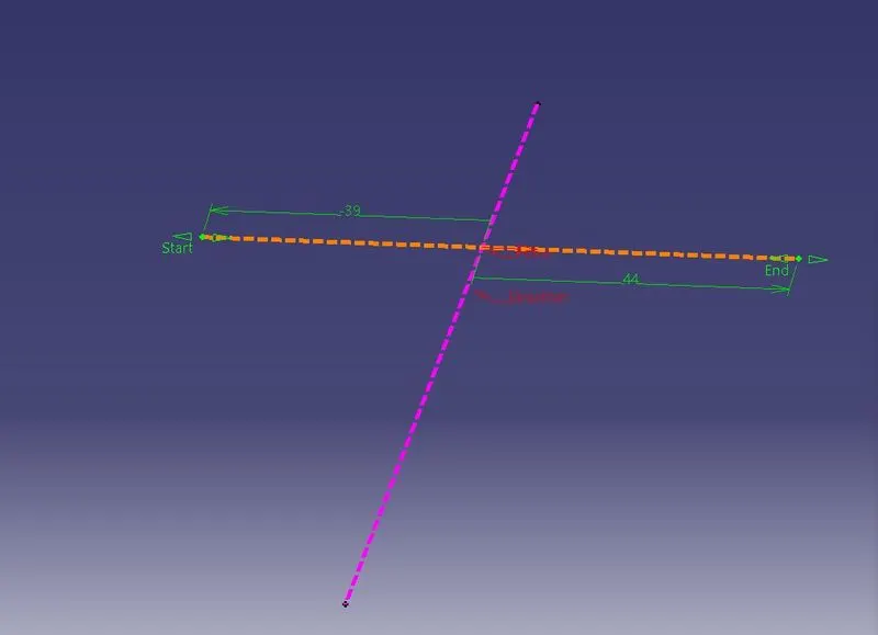
The dog house is not in the direction of mold opening so mold split used. For that split need to create opening axis that is side core axis. Here side core axis created along dog house direction shown like below
Draft Analysis of body
Draft analysis needed for every mold component because at the time of mold ejection the component removed without any difficulty or ejecting component should be safe without any crack and scratch on the surfaces with good aesthetics.
Here, Draft analysis done with respect to 3 .
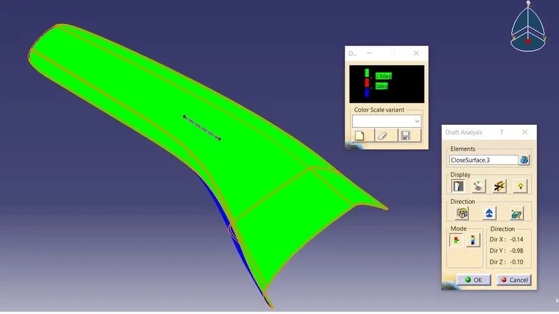
But some places are not cleaing the draft analysis. Which are shown below
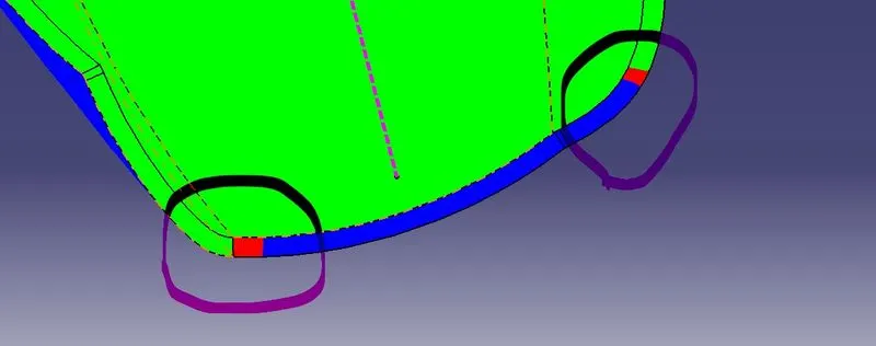
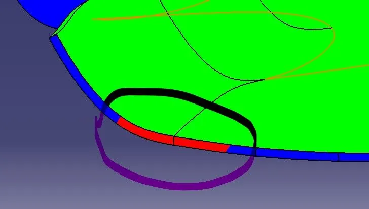
The above shown places are not able to clear the draft analysis. So, I tried to change the angle of class C surface 93° and 87° in those conditions also not able to clear the draft analysis.
So, the class A need modification. After considering with customer modification will be done.
Dog house Draft analysis:
The dog outside done with respect to 1.5°. which is shown shown below all outside surface of dog house clearing the draft analysis.
Inside draft analysis is done with respect to 0.5° which is shown shown below all inside surface of dog house clearing the draft analysis.
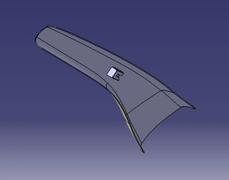
From the above shown draft analysis, the final closed component has negative draft angle in inside and positive draft angle in outside.
ISOMETRIC VIEW
FRONT VIEW
TOP VIEW
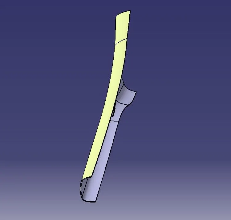
RIGHT SIDE VIEW
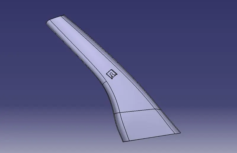
LEFT SIDE VIEW