Week 9 - Project - A pillar Design with Master Section
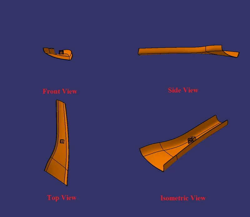
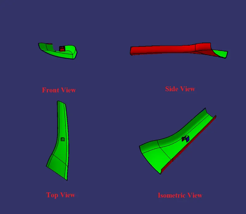
Given CLASS A SURFACE
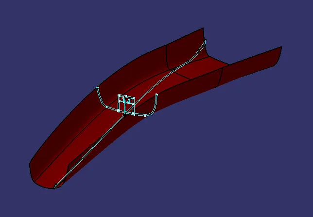
The Way of Creating the Tooling Axis for Y-AXIS of the Component
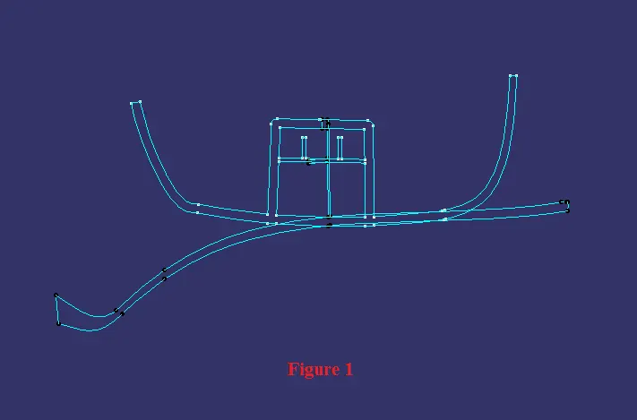
Need to take center of the surface for a Tooling axis. So, here i took the master section which is meet at all surface in a single point which is easy to create a tooling axis as shown in figure 1.
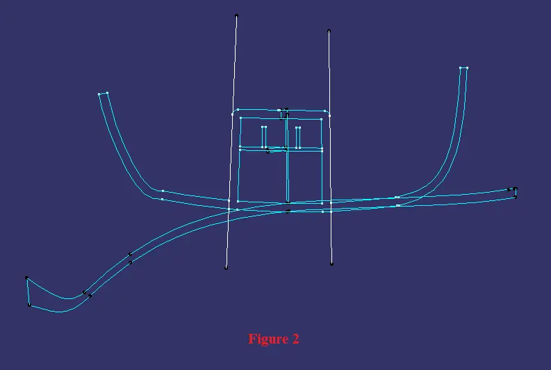
Then i created a line on each side of the inclined line with the help of line command(line definition = point to point) as shown in firgure 2.
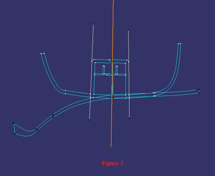
By the uses of two line i created a bisecting line which is showing in orange color with the help of line command(line definition = bisecting = line 1(bisecting line) & line 2(line which is created by surface + point)) as shown in figure 3.
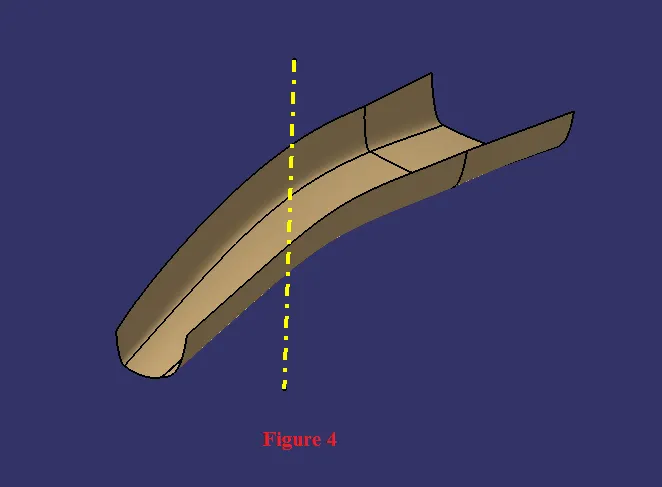
Thus the way i created Tooling Axis for draft analysis as shown in figure 4 which is showing in yellow color center line.
Tooling Axis for Y-Axis/Normal Tooling Axis
The Way of Creating the Tooling Axis for X-AXIS of the Component
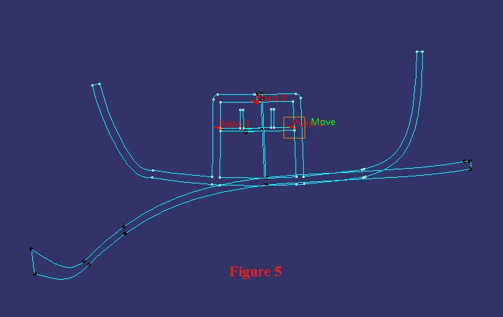
Need to create a another tooling axis for dog house on X-axis because of side core. So, here i took the same master section which is easy to create a side core axis. By the uses of that master section points i created a plane with the help of plane command(plane definition = through three points = point 1 + point 2 + point 3) as shown in firgure 5.
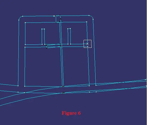
By the uses of that plane i created point with the help of point command(Point definition = on plane) as shown in figure 6.
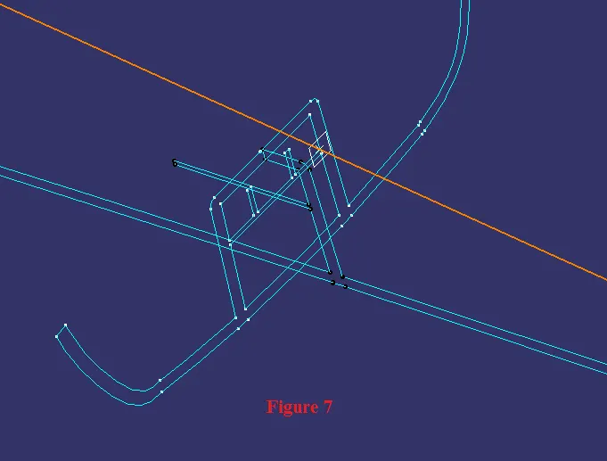
Then i created a line on the point with the help of line command(line definition = point-direction = point + Direction(plane)) which is showing in orange color as shown in firgure 7.
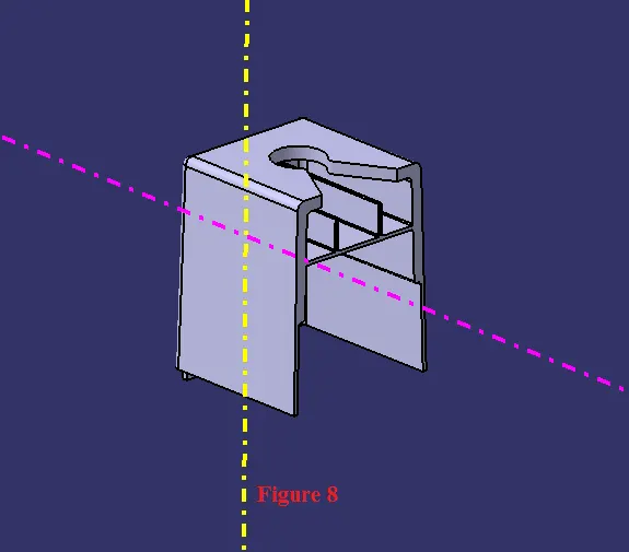
Thus the way i created Tooling Axis on X-axis for draft analysis as shown in figure 8 which is showing in pink color center line.
Tooling Axis for X-Axis/Side Core Axis
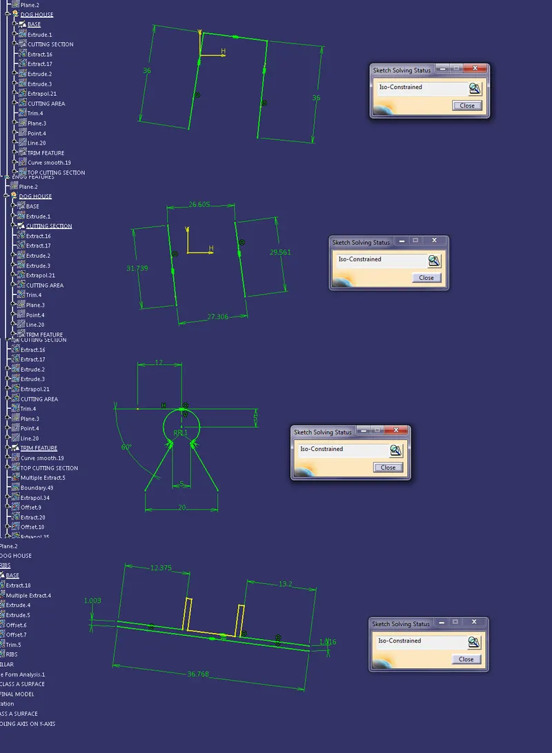
Fully Defined Sketch with sketch solving status dialog box
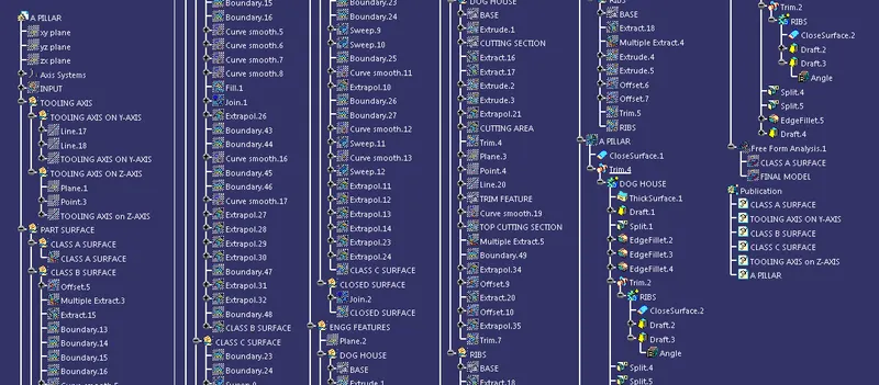
Expanded Tree Structure for the Geometrical Sets and the Part Body
Draft Analysis
Draft Analysis is used to analyze whether our part model created in CAD is manufacturable based on the draft condition applied.
Color scale variant with draft angle for CLASS A SURFACE/Final Component
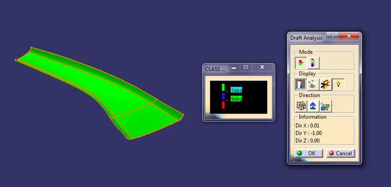
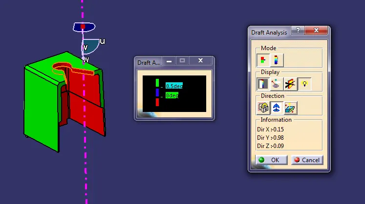
Color scale variant with draft angle for Dog House on Y-Axis
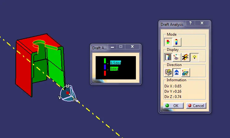
Color scale variant with draft angle for Dog House on X-Axis
Color scale variant with draft angle for Ribs on Y-Axis
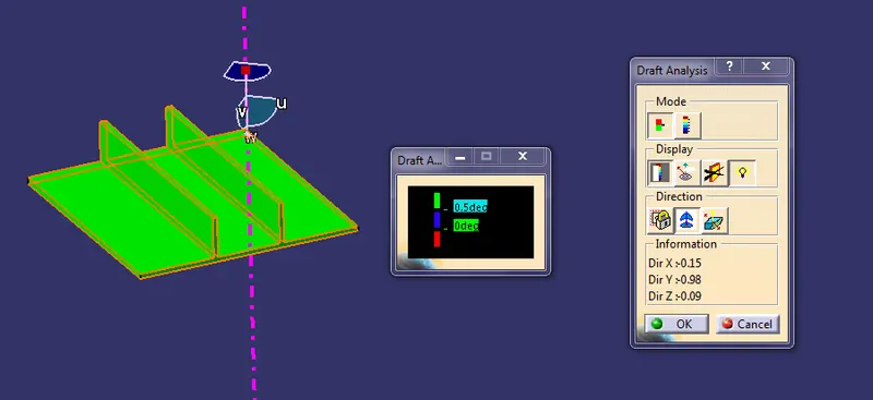
Color scale variant with draft angle for Ribs on X-Axis
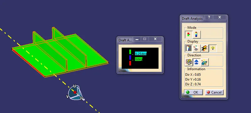
CLASS A SURFACE
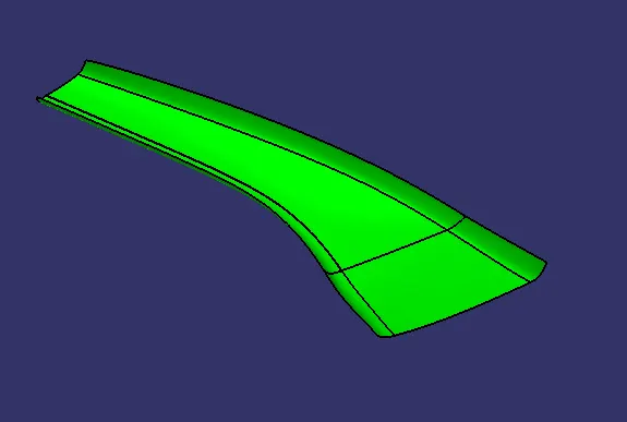
Dog House with the proper color code of the draft analysis on Y-Axis in various orientations
Dog House with the proper color code of the draft analysis on X-Axis in various orientations
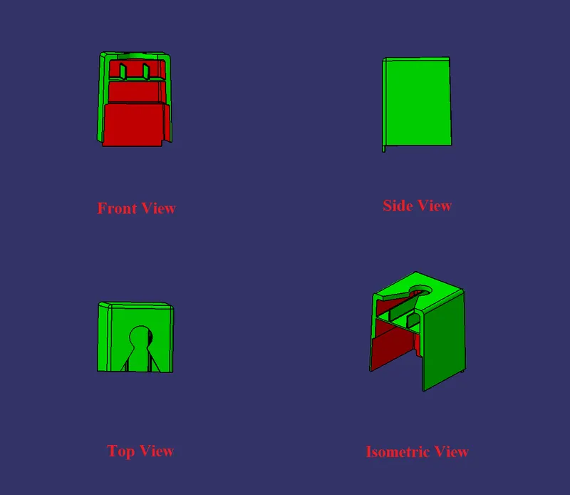
Final solid model design with the proper color code of the draft analysis on Y-Axis
This draft analysis is the normal tooling axis towards to cavity of the final component.
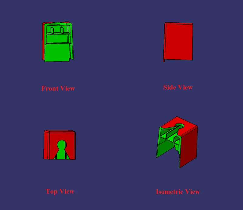
Final solid model design with the proper color code of the draft analysis on X-Axis/side core axis
This draft analysis is occur towards the tooling axis on x-axis/side core axis to make/analysis the dog house for manufacturing.
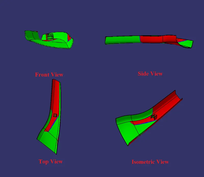
Final solid model in various orientations