Week 9 - Project - A pillar Design with Master Section
AIM
To create an A-pillar using the given CLASS-A surface and Master section.
INTRODUCTION
Back in the day, cars were mostly made of steel and over the decades lightweight alternatives have increasingly found their way into automobile designs. Current economic and ecological concerns make the production of fuel-efficient cars a high priority in the automotive industry. Some other benefits of plastics in vehicles include very little corrosion, extended vehicle life, increased design freedom, greater innovation potential, more versatility in integrating components, greater safety, and greater comfort.
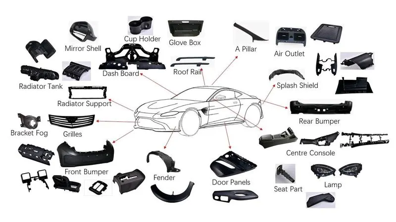
In automotive industries, plastic trims (interior and exterior) play an important role in providing the aesthetics of the automobiles. The figure shows different types of plastic trims used in a passenger car.
The properties of plastic materials which helps in creating complex designs are as follows
- They are light in weight and are chemically stable.
- Easily moulded into different shapes and sizes.
- Good insulation and low thermal conductivity.
- Good impact resistance and they do not rust.
- Good transparency and wear resistance.
- Poor dimensional stability and can be easily deformed.
The pillars on a car with permanent roof body style (such as four-door sedans) are the vertical or nearly vertical supports of its window area or greenhouse—designated respectively as the A, B, C and (in larger cars such as 4-door station wagons and sport utility vehicles) D-pillar, moving from front to rear, in profile view. Car pillars are components that support the structure of an enclosed automobile body. Car pillars are designed to stand in near vertical or inclined positions to support the roof.
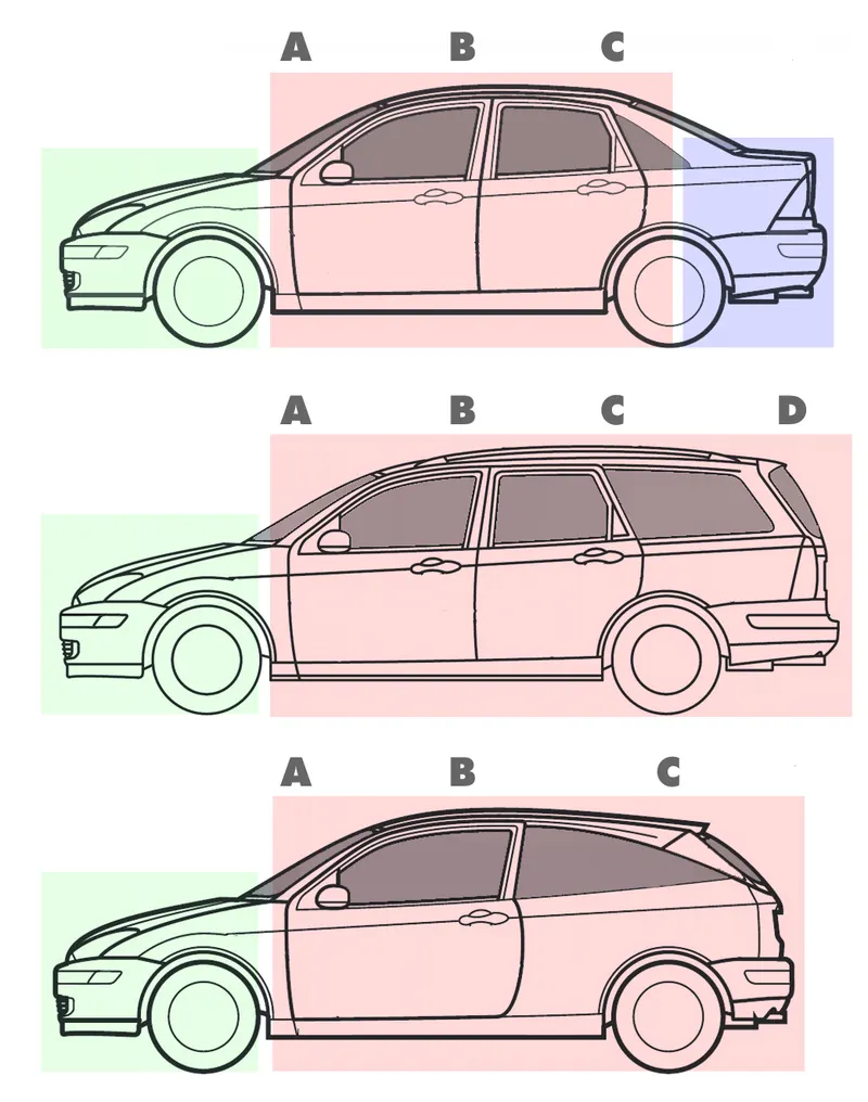
The A-pillars on each side of the windshield come up to be joined together by the header rail across the top of the windshield.

1) DESIGN OBJECTIVE
- Create main tooling axis and side core axis using the given master section.
- Create class B and C surfaces of A pillar and then the final surface.
- Create engineering features on the B side of the solid body part.
- Perform draft analysis for CLASS-A and the final Component.
2) INPUT GIVEN
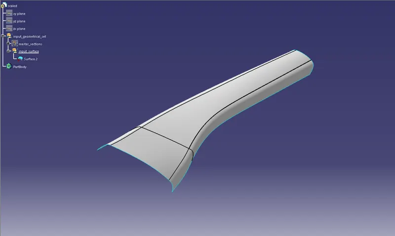
- Class-A surface
Class-A surface means visible surface. It gives the aesthetic of the component which is created by the styling team and gives to the part design engineer to create the part with all engineering aspects.
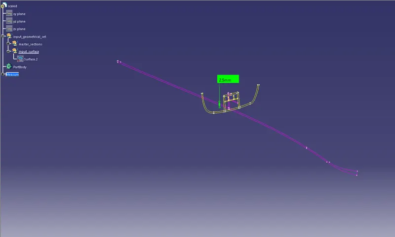
- MASTER SECTION
Master sections are the guides for design requirements which decide the component packaging after technical (Styling, Concept or Class-A) surfaces.
3) DESIGN METHODOLOGY
3.1) CLASS-A quality check
- First step is to check the given A surface visually for finding any patches on it.
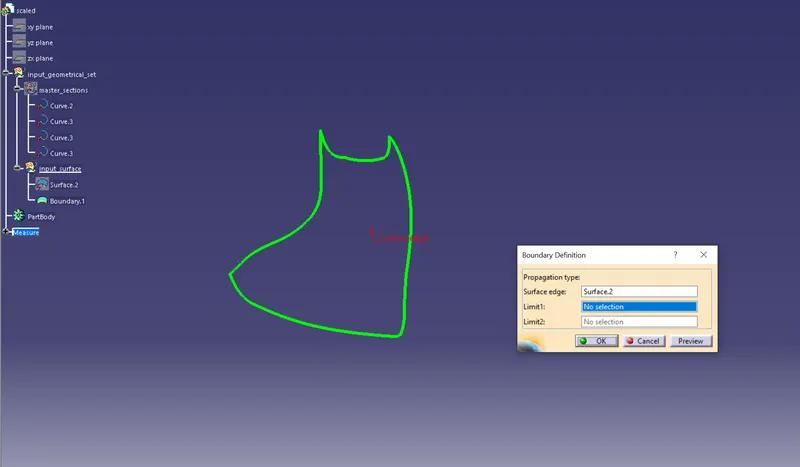
- Using join or boundary commands, ensure the surface quality. If any patches and discontinuity found, initiate rework on the surface.
- Once the surface is improved for further design process, create the tooling axis.
3.2) Tooling Axis Creation
Tooling axis represents the opening and closing of the mold core and cavity during the manufacturing of the components.
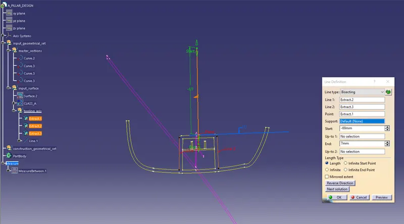
Create tooling axis using the given master section.
- Create a point on the master section.
- Create planes on the given master sections with respect to the point created.
- Using positioned sketch, create lines in the walls of dog house section and then create bisecting line.
- Same way create sketch on the other side wall and then create bisecting line.
- Using the bisecting line 1 and 2, create a new bisecting line which can be selected as the Tooling Axis.
3.3) Draft analysis
The Draft Analysis is a command enables you to detect if the part you drafted will be easily removed. This type of analysis is performed based on colour ranges identifying zones on the analysed element where the deviation from the draft direction at any point, corresponds to specified values.
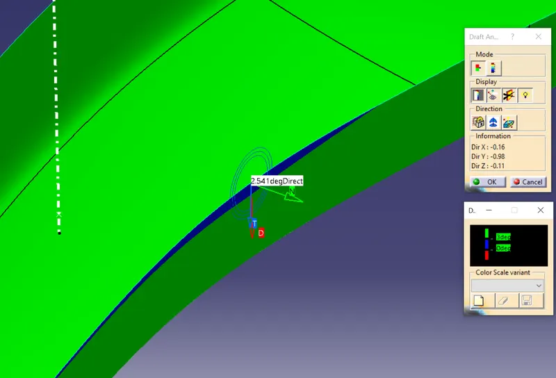
As we know for injection molding the draft on the surface should be positive and greater or equal to 3 degrees. Areas with the draft less than 3 degrees are a bit difficult and costly to manufacture.
Procedure for performing the draft analysis are as follows
- Change the view mode of the component to be in customized parameter mode and then select the shading mode as materials.
- Then open the featured draft analysis tool from the insert menu.
- Then click on use the compass to define the current drafting direction and then drag and align the compass on the Tooling axis.
- Then lock the draft direction and perform draft analysis by clicking on the component.
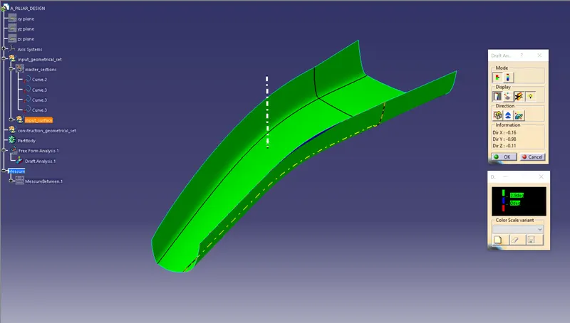
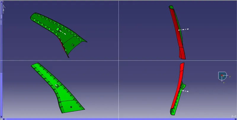
- The green colour shows the positive daft tooling direction and the given surface passes the draft analysis.
- Click on the analyses under the running point to check the draft analysis on the individual faces. It shows how much draft on specific points when we move the cursor point.
- Draft analysis of CLASS-A surface.
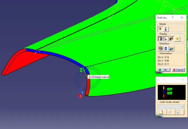
- Blue colour shows the wall has a draft value of 2.541 degrees at that particular region.
3.4) CLASS-B surface creation
Class-B surface means thickness of a part it is not visible and is inside part. In other words, Class-B surface is a surface below a certain thickness from the class-A surface. This is the surface that contains engineering aspects of a model.
- From the given master section, it is clear that the thickness of the component should be 2.5mm. For that, offset the class A surface about 2.5 mm inward direction to meet the required thickness.
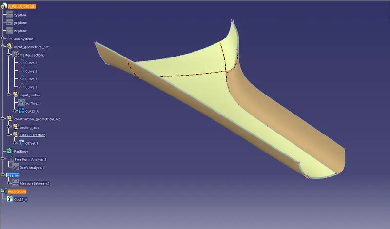
- Work on the patches created during the offset by using the sweep command.

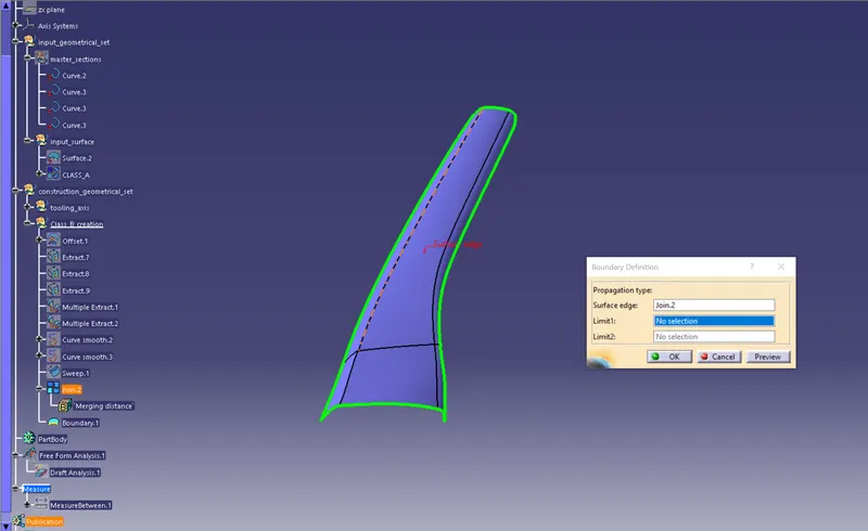
- Join the patch surface to the offset surface and then Ensure the quality of the Final B surface using the Boundary command.
3.5) CLASS-C surface creation.
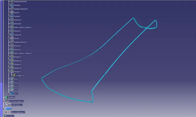
Surface that joins class-A and class-B surfaces is class-C surface. Class C is often specified for interior surfaces not readily visible, surfaces that will be covered by another part when assembled
- C surface can be created using the sweep surface command and multi section surface commands.
- Use the reference as the surface as well as the tooling axis at required swept surfaces.
3.6) Final surface Creation Procedure
- Final surface created should be a fully closed surface with no gaps in between.
- First step is to join the CLASS A and C surfaces using the Join command.
- Then extrapolate the CLASS B surface to avoid gaps when trimming it with the Joined A+C surface.
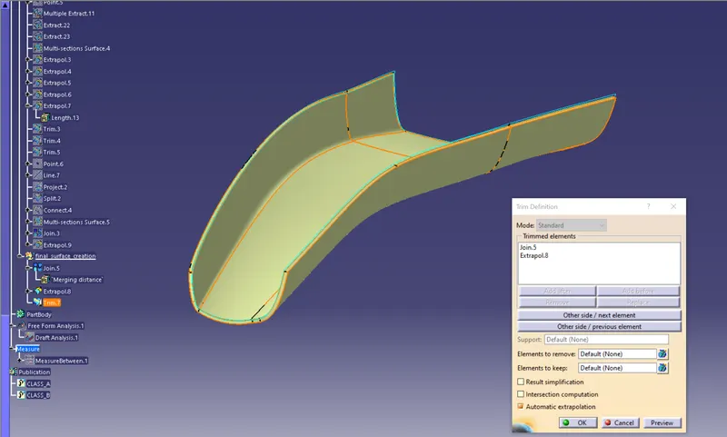
- After trimming the extrapolated B surface and Joined A+C surface, ensure the quality of the final surface using boundary command.
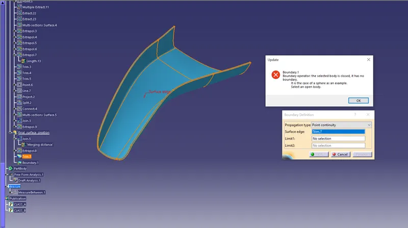
3.7) Make a solid part body using the close surface command in the part design workbench
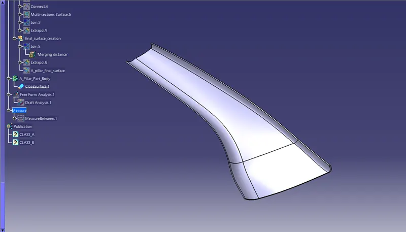
- Draft analysis of A pillar body part
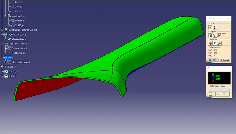
- the area which has a negative draft value on the c surface
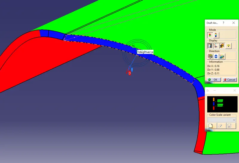
3.8) Attachment features Creation
- All the attachment features are added to the main body using Boolean operations.
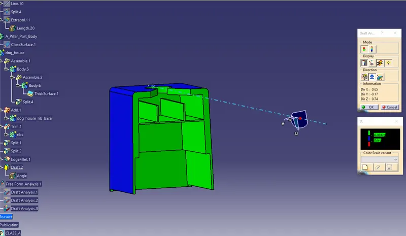
- DOG HOUSE
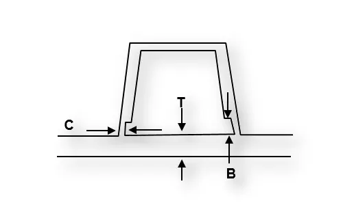
Dog houses are designed to avoid SINK MARK created on the CLASS-A surface by screw bosses and to solve the length issues when giving screw bosses which need to be assembled to other components.
It is also useful when perpendicular screw bosses are required on the part to the tooling direction.
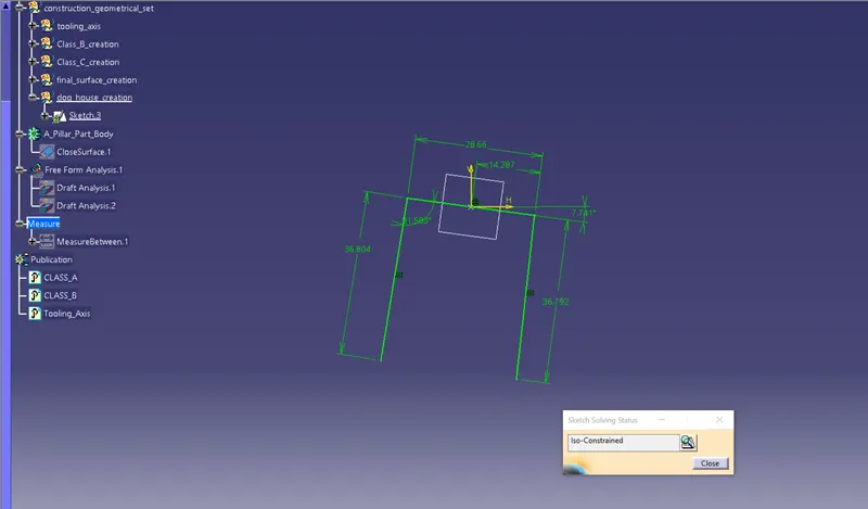
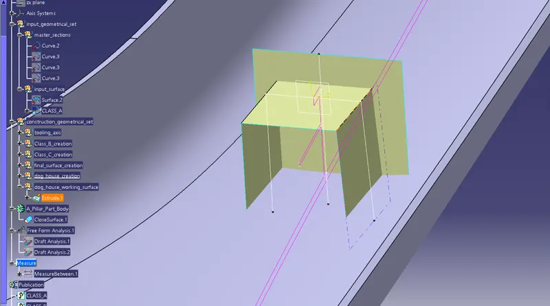
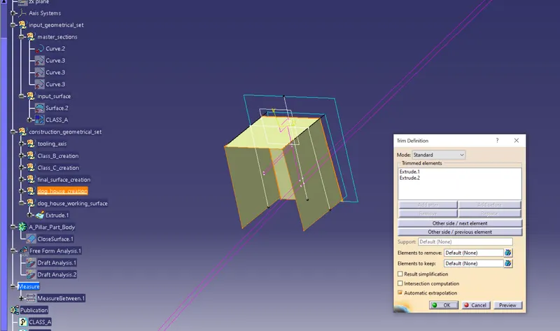
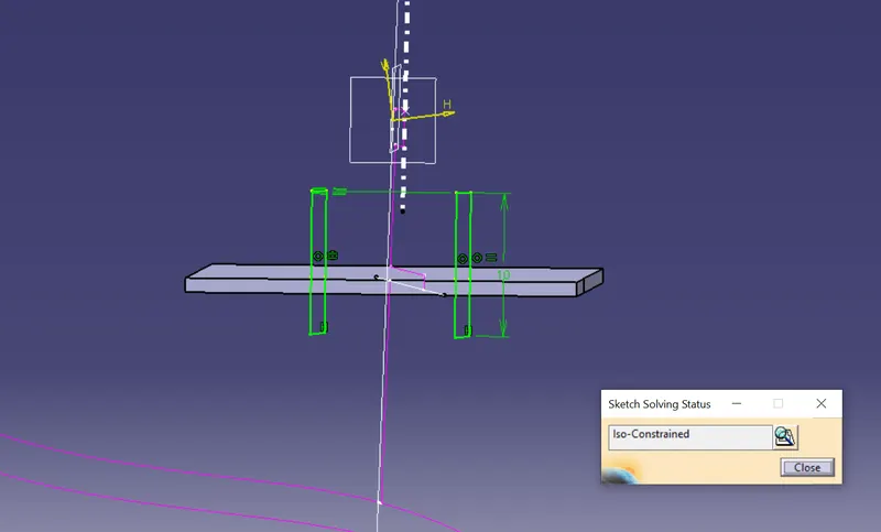
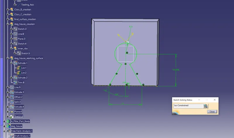
Here the dog house is created using the Master section
- Create a positioned sketch on plane created on the master section.
- Extract the required master section and isolate it. Then given the constrains and extrude the sketch.
- Side core Axis
Since the dog house's inner walls will not be cleared in the main tooling direction, we need to create the tooling axis for the side core. A min of 0.5 degrees draft is provided on all the walls.
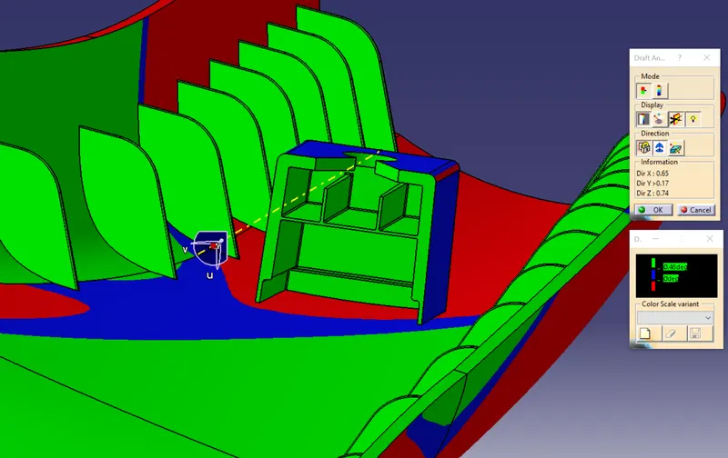
- Draft analysis of Dog House using the Side Core Axis
- Given Draft Value is 0.5 degrees
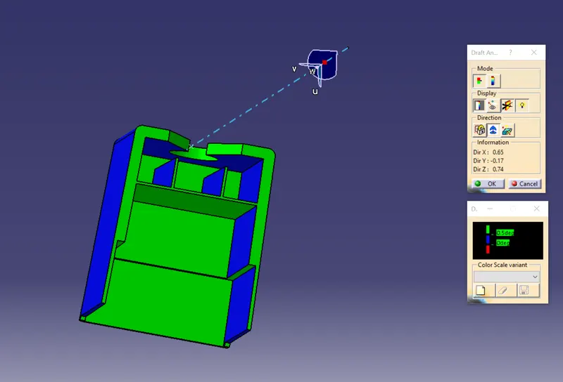
- Draft analysis with 0.48 draft value
- LOCATOR
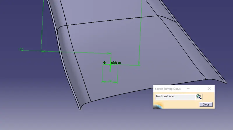
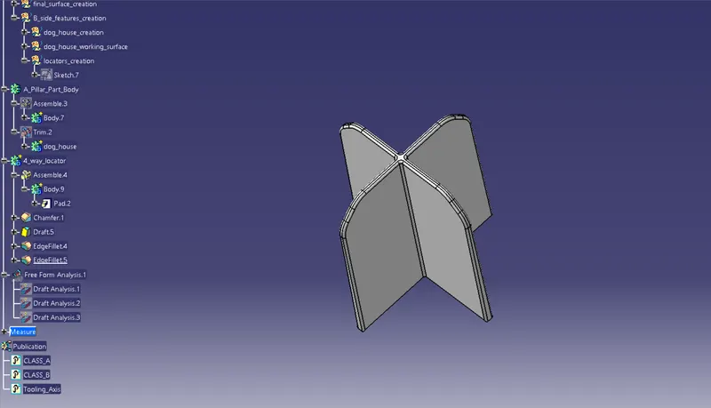
Locating pins are the rib like structures on the B surface which are used to position the child part with parent part while assembling and also helps to arrest the degrees of freedom of the part.
Design guidelines of ribs should be followed during the locator designing process.
I have created a 4-way locator for the A pillar component.
- RIBS for the side walls
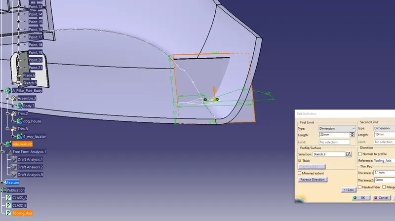
These ribs are designed to add strength and stiffness to the part locally by not adding excess weight to the body.
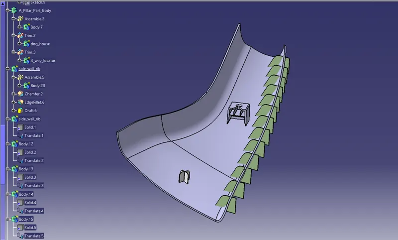
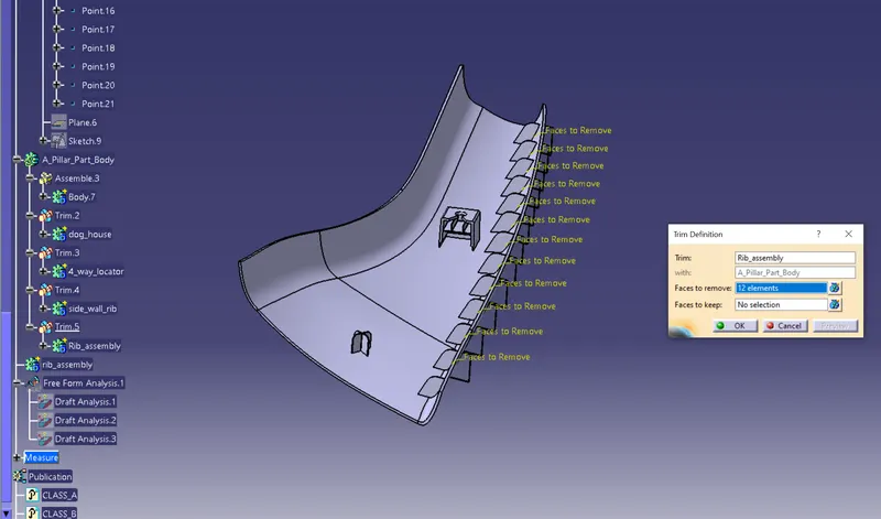
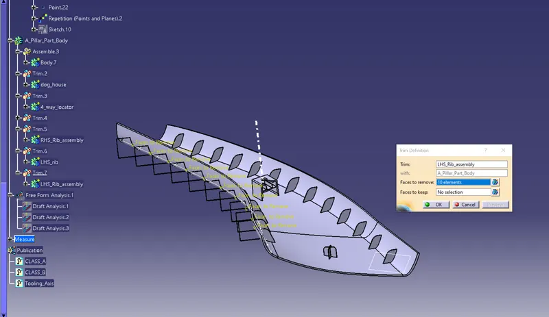
- Final A pillar Component with all the attachment features
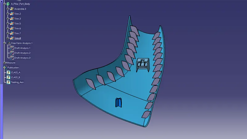
- 3D Part model in various orientations (Isometric, Front, Side, and Top View)
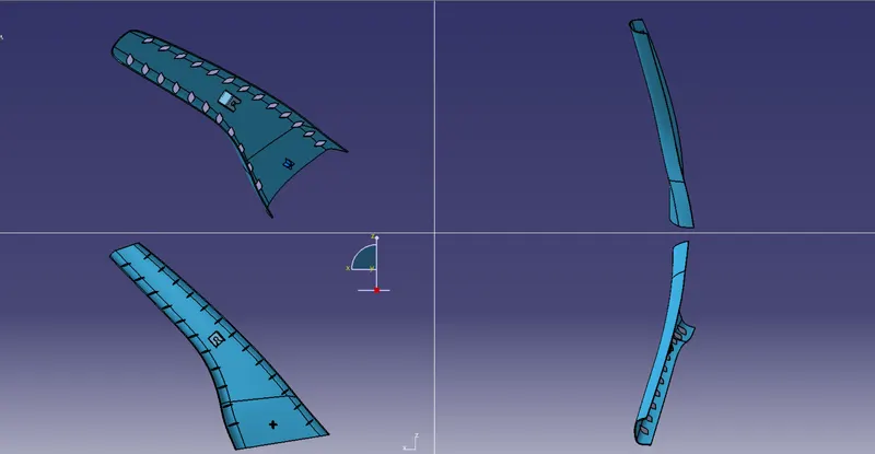
3.9) DRAFT ANALYSIS of final component
- Using Main Tooling Axis
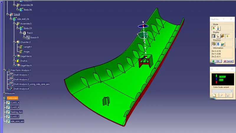
- Using Side Core Axis
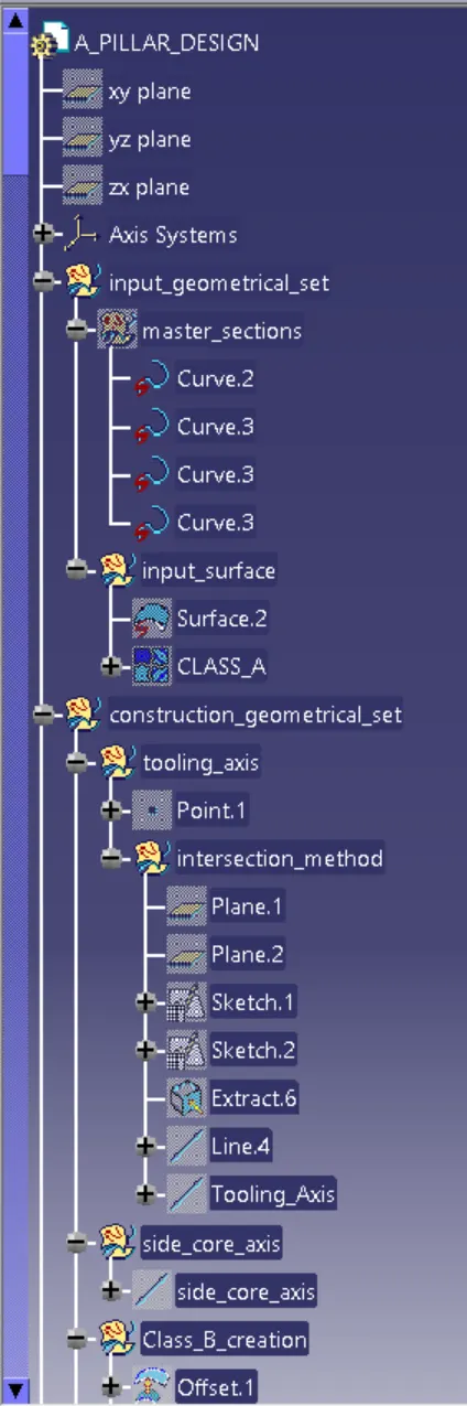
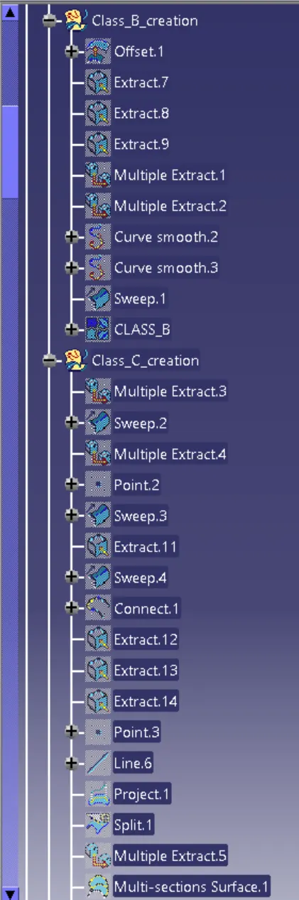
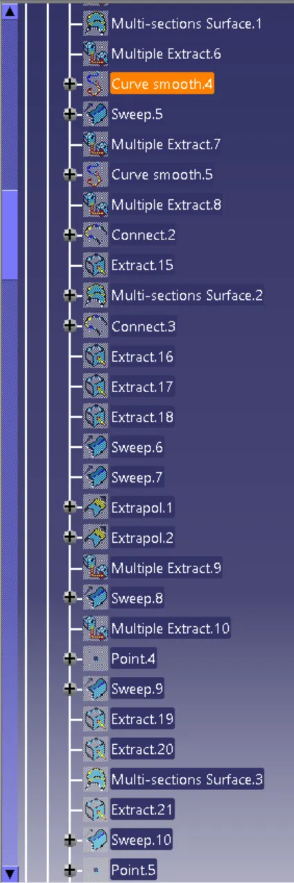
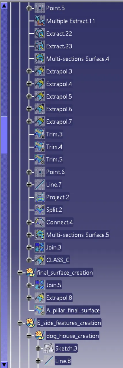
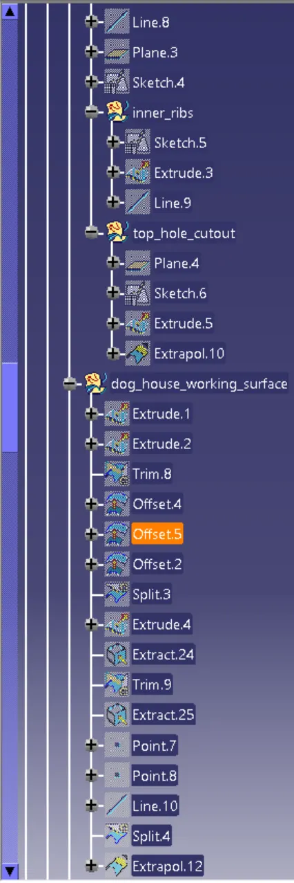
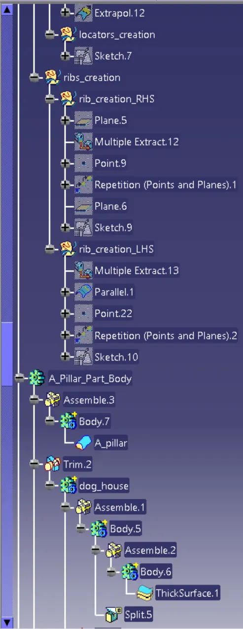
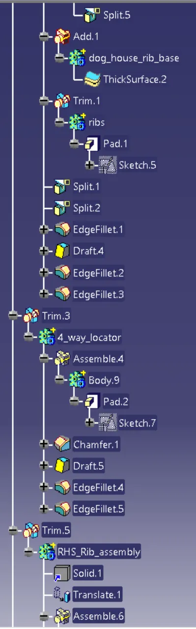
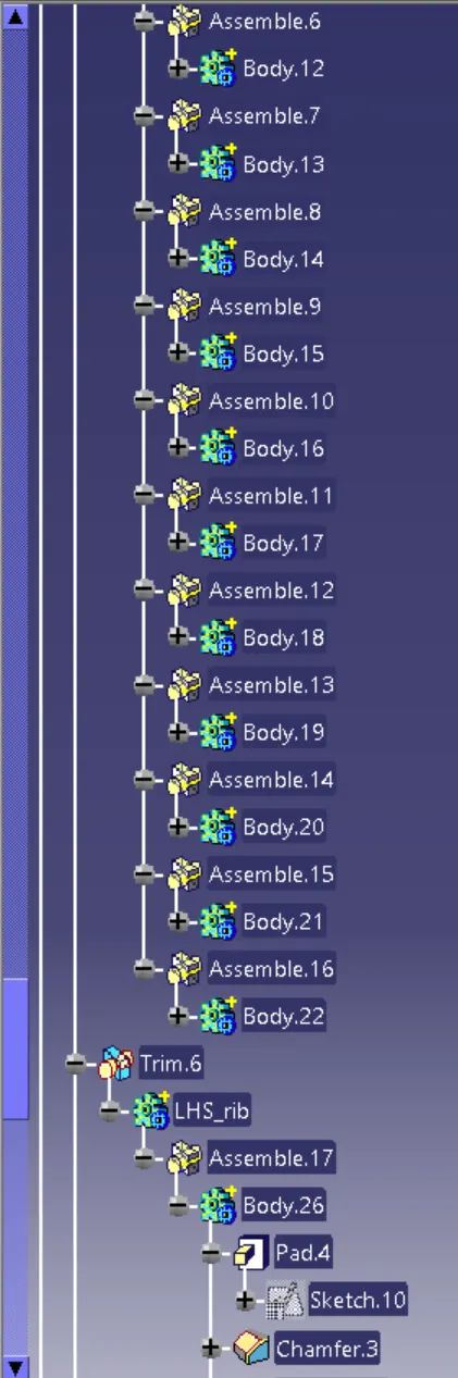
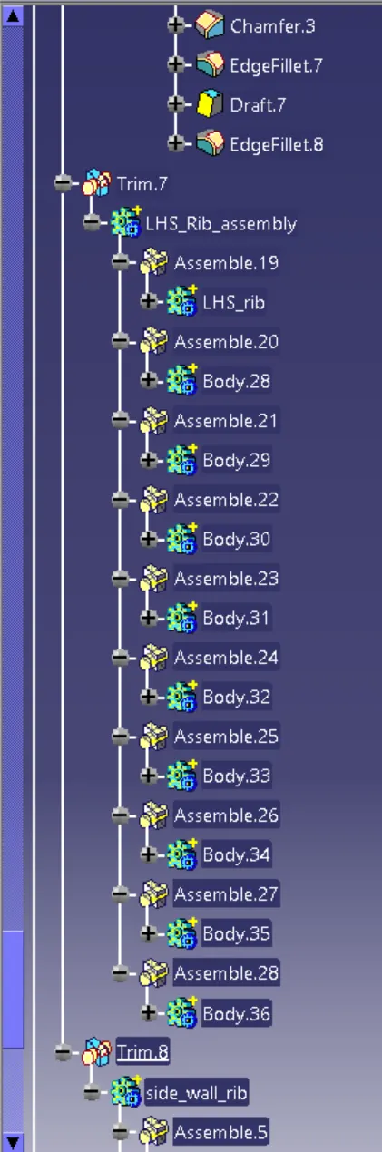
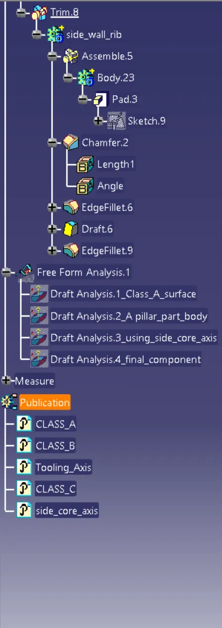
- The expanded Tree Structure for the geometrical set and the Part Body
Conclusion
A-pillar design has been successfully completed using the given CLASS-A surface and Master section by considering the design rules. Also performed draft analysis on the class-A surface and final component.